 注: 建议图片大小150px*50px

丨
English
注: 建议图片大小150px*50px Views: 0 Author: Site Editor Publish Time: 2026-08-10 Origin: Site


Aluminum presents fundamental metallurgical challenges during thermal processing. Its high thermal conductivity and intense infrared reflectivity historically made it one of the most difficult metals to cut cleanly. When a laser beam strikes an aluminum surface, the material immediately attempts to reflect the light while simultaneously drawing heat away from the cut zone. This rapid heat dissipation requires immense energy to overcome. Poor edge quality directly compromises dimensional tolerances. Dross accumulation, micro-cracking, severe striations, and thermal distortion increase scrap rates and force expensive secondary machining. You cannot afford to spend hours manually deburring parts or rejecting warped components due to improper cutting parameters. Achieving burr-free, smooth edges relies on a strict matrix of laser parameters, assist gas selection, and specialized equipment. Operators must balance cutting speed with laser power while utilizing high-pressure assist gases to evacuate molten material instantly. aluminum laser cutting demands precise control over every machine variable to produce pristine edges that require zero secondary processing.
Speed vs. Power Correlation: In aluminum processing, faster cutting speeds generally yield smoother edges, necessitating high-wattage laser systems to maintain velocity without losing penetration.
Assist Gas is Critical: High-pressure Nitrogen is the industry standard for achieving an oxide-free, bright edge, whereas Oxygen or compressed air introduce thermal and chemical variables that degrade edge quality.
Alloy and Thickness Dictate Parameters: Edge quality outcomes vary significantly between common grades (e.g., 5052 vs. 6061) and thicknesses, with material over 1/4-inch requiring distinct focal and speed adjustments.
Equipment Architecture Matters: Modern fiber lasers with built-in back-reflection protection have largely replaced CO2 lasers for aluminum, offering superior wavelength absorption and edge consistency.
Visual Diagnostics: A smooth, bright edge is the primary indicator of correct power balance and optimal gas flow, whereas rough, striated edges signal parameter or maintenance failures.
Aluminum rapidly dissipates heat away from the cut zone. This high thermal conductivity means the metal acts as a massive heat sink, pulling thermal energy away from the laser beam's focal point the millisecond it strikes the surface. To achieve a clean cut, the laser must deliver immense localized energy to melt the material instantly before the surrounding area absorbs enough heat to warp. Failure to balance energy input with cutting speed causes a wide, destructive Heat-Affected Zone (HAZ). A large HAZ introduces residual thermal stress, altering the mechanical properties of the metal and causing thin sheets to distort permanently. Controlling the HAZ requires precise power modulation and rapid beam movement. If an operator runs a 4kW laser at 100 inches per minute on 1/8-inch aluminum, the heat spreads faster than the cut advances. The metal warps, the kerf widens, and the part fails inspection. You must push the feed rate to outrun the thermal conduction.
Standard laser systems face significant danger from back-reflection when processing aluminum. In its solid state, aluminum reflects a large percentage of infrared light. Once the laser breaches the surface, the molten aluminum acts as a highly efficient mirror. This molten pool can reflect the concentrated laser beam directly back up through the nozzle, up the fiber cable, and into the sensitive internal optics. Back-reflection causes micro-stuttering in the cut path, degrading edge smoothness and potentially destroying expensive collimating lenses and cutting heads. Managing this reflectivity is a core requirement for maintaining consistent edge quality. Without optical isolators, the machine will repeatedly fault out, leaving jagged start-and-stop marks along the perimeter of the part.
Dross consists of resolidified molten aluminum clinging to the bottom edge of the cut part. It forms when the cutting process fails to evacuate the melt pool fast enough. Aluminum has a high surface tension when molten. If the gas pressure drops below 15 bar, or if the focal length is set incorrectly, the molten metal sags and hardens before it clears the kerf. Hard dross requires mechanical grinding to remove, adding significant labor time and altering the final dimensions of the part. Soft dross might break off easily but still leaves a jagged, unacceptable bottom edge. Preventing dross requires a perfect combination of high-pressure assist gas, correct nozzle standoff, and optimal cutting speed to shear the molten metal off the bottom edge before it freezes.
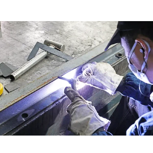
Mastering aluminum sheet fabrication requires operators to manipulate several interconnected machine variables. Changing one parameter always impacts the others. You cannot adjust gas pressure without re-evaluating your feed rate.
A counterintuitive rule governs aluminum processing: faster cutting speeds reduce the time heat has to spread, resulting in a smoother edge. Slow cutting allows the high thermal conductivity of the metal to draw heat outward, widening the kerf and creating a rough, melted appearance. Achieving these high speeds requires high-wattage equipment. Systems ranging from 6kW to 12kW and above are necessary to maintain continuous penetration at high velocities. If an operator attempts to cut fast with insufficient power, the beam will fail to pierce the bottom of the sheet, causing a blowout and ruining the part. Pushing an 8kW laser to 800 inches per minute on thin gauge aluminum produces a mirror-like edge because the beam vaporizes the metal before the surrounding material even registers the heat.
Nitrogen (N2) serves as the industry standard assist gas for aluminum. As an inert shielding gas, Nitrogen blows away molten material rapidly without fueling the burning process. This results in a clean, silver edge free of oxidation. High purity Nitrogen (99.99% or higher) delivered at high pressure (typically 18 to 22 bar) ensures the melt pool clears the kerf instantly. Oxygen (O2) and compressed air are generally avoided for precision parts. Oxygen creates an exothermic reaction, burning the aluminum rather than simply melting it. This causes micro-pitting, heavy oxidation, and rougher surface finishes. Compressed air contains moisture and trace compressor oils that introduce impurities into the cut edge, leading to porosity if the part is later welded.
Setting the correct focal point dictates the shape of the kerf. For aluminum, operators typically set the focal point slightly below the surface of the material. A negative focal position (e.g., -1.5mm to -2.5mm for 1/4-inch aluminum) ensures a wider kerf at the bottom of the cut. This V-shape aids in the rapid ejection of molten metal and prevents dross accumulation. Nozzle condition and standoff distance directly impact gas flow dynamics. A damaged nozzle orifice creates turbulent gas flow, leading to edge striations and inconsistent dross removal. Maintaining a tight, consistent standoff distance (usually 0.5mm to 0.8mm) ensures the assist gas hits the melt pool with maximum kinetic energy.
Operators must know how to read the cut edge to troubleshoot parameter issues. A smooth, bright finish indicates a correct power balance and optimal gas flow. The striation lines should be nearly vertical and very fine. A rough, heavily striated edge points to suboptimal cutting speeds or incorrect focal length. If the striations trail heavily backward, the cutting speed is likely too fast for the applied power. If the top edge is rounded or melted, the focal position is too high or the laser power is excessive. Yellow or brown discoloration on the edge signals gas impurities or a loss of Nitrogen shielding.
Edge Quality Troubleshooting Matrix
| Visual Symptom | Probable Cause | Corrective Action |
|---|---|---|
| Heavy bottom dross (hard to remove) | Low gas pressure or slow cutting speed | Increase Nitrogen pressure to 18+ bar; increase feed rate. |
| Melted or rounded top edge | Focal point too high or excessive laser power | Lower focal point into the material; reduce wattage slightly. |
| Striations trailing heavily backward | Cutting speed too fast for current power | Decrease feed rate or increase laser power. |
| Yellow/brown edge discoloration | Oxygen contamination in assist gas | Check Nitrogen manifold for leaks; verify gas purity. |
| Inconsistent edge quality on different axes | Nozzle is not centered to the laser beam | Perform a tape shot and re-center the nozzle. |
The fundamental difference between laser technologies lies in their light wavelengths. Fiber lasers operate at a wavelength of 1.06 µm. Aluminum absorbs this shorter wavelength highly efficiently, allowing the beam to couple with the material and initiate the melt rapidly. CO2 lasers operate at a wavelength of 10.6 µm. Aluminum reflects a massive percentage of this longer wavelength, making the initial piercing process volatile and inefficient. The superior absorption rate of fiber lasers translates directly to faster cutting speeds, narrower kerfs, and cleaner edges. You simply cannot achieve the same edge quality on a CO2 machine without running at a fraction of the speed and risking severe back-reflection damage.
Modern fiber lasers utilize built-in optical isolators and specialized sensors to safely cut reflective materials. If a back-reflection event occurs, these sensors detect the reflected light and instantly shut off or modulate the beam before it damages the oscillator. This protection allows fiber lasers to process aluminum without interrupting the cut cycle. Continuous, uninterrupted cutting ensures smooth edges. Older systems lacked these advanced protections, often requiring operators to use suboptimal parameters just to protect the machine, which inherently degraded edge quality and left heavy dross on the bottom of the sheet.
Regular machine maintenance acts as a non-negotiable factor in maintaining edge quality. Dirty optics scatter the laser beam, reducing power density at the focal point and causing immediate dross formation. Chiller calibration ensures the cutting head maintains a stable temperature. If the chiller temperature fluctuates, the internal lenses experience thermal lensing—they physically expand and change shape. This shifts the focal point mid-cut, suddenly causing dross on a part that was cutting perfectly five minutes ago. Precise daily nozzle centering guarantees the assist gas flows perfectly concentric to the laser beam. Failing to center the nozzle results in directional cut variations, where the edge quality looks perfect on the X-axis but terrible on the Y-axis across high-volume production runs.
To maintain peak edge quality, operators must follow a strict daily maintenance routine:
Inspect and center the nozzle using tape shots before running any production batch.
Remove and inspect the protective cover glass for spatter or dust contamination.
Verify the chiller water levels and ensure the temperature is locked at exactly 22°C.
Check the nitrogen gas purity at the manifold to prevent oxidation on the cut edge.
Producing high-quality laser cut aluminum parts requires a deep understanding of how different alloys react to intense thermal energy.
Aluminum Alloy Laser Cutting Characteristics
| Alloy Grade | Primary Alloying Element | Cutability Rating | Edge Quality Characteristics |
|---|---|---|---|
| 5052 | Magnesium | Excellent | Produces clean, bright edges with minimal dross. Highly formable post-cut. |
| 6061 | Silicon / Magnesium | Good | Cuts well but requires precise thermal control to avoid micro-cracking on the edge. |
| 7075 | Zinc | Fair | Higher zinc content affects melt pool behavior. Prone to rougher edges and requires slower speeds. |
| 3003 | Manganese | Excellent | Very clean cuts, low thermal distortion, ideal for thin sheet applications. |
Different aluminum alloys exhibit distinct cutting behaviors based on their chemical composition. The 5052 alloy offers excellent formability and cuts cleanly, making it a favorite for sheet metal enclosures and brackets. The 6061 alloy serves as a standard structural material; it cuts well but requires precise thermal control. The silicon and magnesium content in 6061 makes it susceptible to micro-cracking along the cut edge if the heat input is too high. Furthermore, 6061-T6 is tempered. The heat of the laser locally anneals the edge, dropping its yield strength. You must cut fast to keep this annealed zone under 0.010 inches wide. The 7075 aerospace-grade alloy contains a higher zinc content. Zinc vaporizes rapidly under the laser, creating a plasma cloud that alters the melt pool behavior. This makes it challenging to achieve a perfectly smooth edge without specialized parameter adjustments and slower feed rates.
A critical threshold exists around 1/4-inch (6.35mm) thickness. Cutting thick aluminum requires significantly slower speeds, higher wattage, and larger nozzle diameters to maintain accuracy. As the material gets thicker, evacuating the molten metal becomes exponentially more difficult. The assist gas must push the heavy melt pool all the way down through a deep kerf. If the parameters are slightly off, severe bottom-edge dross forms immediately. Operators must shift their focus from speed to melt ejection, often increasing the nozzle standoff slightly and utilizing larger orifice nozzles (up to 3.0mm) to shape the gas flow for deep penetration. Pushing past 1/2-inch thickness requires massive power (12kW+) to maintain an edge that doesn't look like it was chewed through by a plasma torch.
Industrial realities contrast sharply with hobbyist workarounds regarding surface preparation. DIY forums often suggest coating aluminum plates in flat black paint or milk of magnesia to reduce surface reflectivity before cutting. In a professional manufacturing environment, these methods are entirely unviable. They introduce contamination, require extensive post-cut cleaning, and slow down production. True industrial precision relies on raw material quality, proper storage to avoid heavy natural oxidation, and the utilization of advanced fiber laser technology capable of handling raw, bare aluminum sheets without artificial surface treatments. Store your aluminum sheets indoors, away from moisture, to prevent the thick aluminum oxide layer that can disrupt the laser piercing process.
When sourcing partners for precision cutting applications, engineering teams must evaluate the vendor's technical capabilities and quality control standards.
Success criteria in precision manufacturing rely on measurable data. A highly controlled aluminum laser cut should achieve a surface roughness (Ra) between 3.2 and 6.3 μm, depending on the material thickness and specific alloy. Surface roughness is measured with a profilometer, where a stylus drags across the cut edge to measure the microscopic peaks and valleys. Achieving a low Ra value ensures a stress-free interaction for downstream assembly. Rough edges create stress concentrators that can lead to fatigue failure in structural components. Vendors must demonstrate their ability to hold tight dimensional tolerances (often +/- 0.005 inches) while simultaneously maintaining strict surface roughness standards across the entire perimeter of the part.
Financial trade-offs heavily favor vendors who master laser parameters. A vendor with optimized settings provides "as-cut" parts that completely bypass the deburring department. These parts require no grinding, sanding, or oxide layer removal before moving directly to the press brake or downstream welding operations. Eliminating secondary processing lowers the overall cost-per-part and drastically reduces lead times. A vendor offering a lower upfront cutting price but delivering dross-heavy parts will ultimately cost more due to the internal labor required to clean the edges before assembly.
A reliable fabrication partner implements rigorous quality assurance protocols. Look for facilities that conduct documented first-article inspections using coordinate measuring machines (CMM) or optical comparators. They should utilize automated optical inspection tools to verify edge quality and hole geometry. Strict assist-gas purity standards are essential; vendors should monitor their Nitrogen supply manifold to prevent oxygen contamination. Request to see documented machine maintenance logs. A vendor that meticulously cleans optics, changes filters, and calibrates chillers will consistently produce superior aluminum parts.
To implement these edge quality controls and optimize your next production run, execute the following steps:
Submit your CAD files to a qualified fabrication partner for a comprehensive manufacturability review and parameter test cut.
Establish clear, measurable surface roughness (Ra) requirements and acceptable dross limits in your initial RFQ documentation.
Audit the vendor's machine maintenance logs, specifically checking their optic cleaning schedules and assist-gas purity standards.
Request a first-article inspection report utilizing a coordinate measuring machine to verify dimensional accuracy before authorizing high-volume production.
A: High-purity Nitrogen (N2) is the optimal assist gas for cutting aluminum. It acts as an inert shield, blowing away molten material without causing oxidation or exothermic burning. This results in a clean, bright, and silver edge that requires no secondary cleaning or mechanical deburring.
A: Dross forms when molten aluminum is not evacuated from the kerf fast enough. This occurs due to low assist gas pressure, incorrect focal length, or cutting speeds that do not match the applied laser power. The high surface tension of aluminum causes the sluggish melt pool to resolidify on the bottom edge.
A: Modern high-wattage fiber lasers can cleanly cut aluminum up to 1 inch thick. However, the most consistent, burr-free edge quality is typically achieved on sheets 1/4-inch thick or thinner. Thicker plates require specialized nozzle setups and slower speeds to manage the massive melt pool.
A: Yes. Faster cutting speeds generally produce smoother edges on aluminum. High speeds reduce the time heat has to spread into the surrounding material. This minimizes the heat-affected zone, prevents the kerf from widening, and stops the material from melting excessively along the cut path.
A: Yes, provided you use a modern fiber laser equipped with optical isolators and back-reflection sensors. These safety mechanisms protect the machine's internal optics from reflected light. If a reflection occurs, the system modulates the beam instantly, allowing for continuous, smooth cutting of highly reflective grades.


