 注: 建议图片大小150px*50px

丨
English
注: 建议图片大小150px*50px Views: 0 Author: Site Editor Publish Time: 2026-10-21 Origin: Site


A fraction of a degree in a bend can misalign an entire chassis assembly. Achieving exact dimensions requires knowing your material limits from the inside out. In this technical guide, we break down the exact tolerances CNC press brakes achieve for steel and aluminum. You will also find actionable design strategies to improve manufacturability and eliminate downstream assembly failures.
Key Takeaways
Standard Baselines: Industry norms typically range from ±0.010 to ±0.030 inches for dimensional accuracy, and ±0.5 to ±1.0 degrees for bend angles. These figures depend heavily on sheet gauge and tooling conditions.
Material Behavior: Aluminum requires careful consideration of grain direction and cracking risks, especially in harder tempers like 6061-T6. Steel variants demand precise calculations for springback due to higher yield strengths.
Blank Preparation: The dimensional accuracy of flat blanks prepared prior to bending directly dictates the final precision of the formed component.
Design for Manufacturability: Maintaining consistent inside bend radii and keeping cutouts safely away from bend lines are mandatory requirements for achieving tight tolerances.
Precision bending is a foundational process within modern Sheet Metal Fabrication. It utilizes computer-numerically-controlled press brakes equipped with a punch and a V-die to apply immense tonnage to a flat sheet of metal. This force drives the material into a specific angular geometry. While modern electric press brakes boast positioning repeatabilities of ±0.0004 inches at the ram, the actual tolerance of the finished part is ultimately dictated by material physics and shop-floor variables.
In engineering and quality control, bending tolerances are categorized into two primary metrics. Dimensional tolerance refers to the acceptable variance in the physical length of a flange, which is the flat section of metal extending from the bend. For example, a flange designed to be 2.000 inches might have a dimensional tolerance of ±0.015 inches. Angular tolerance defines the acceptable variance in the degree of the bend itself. A 90-degree bend with an angular tolerance of ±0.5 degrees is perfectly acceptable if the final measurement falls between 89.5 and 90.5 degrees.
Furthermore, tight tolerances are not merely aesthetic preferences. They are critical functional requirements. In complex mechanical assemblies or aerospace chassis, a deviation of a single degree in a foundational bend can result in misaligned mounting holes further down the assembly line. This misalignment often necessitates costly manual rework or outright part rejection.
When specifying tolerances on an engineering drawing, it is crucial to differentiate between standard industry capabilities and tight, high-precision requirements. Looking at current manufacturing trends, there is a massive surge in demand for miniaturized, high-density electronic enclosures and lightweight aerospace components. This shift is pushing CNC bending tolerances to their absolute limits. To keep up, the industry is rapidly transitioning toward automated, electric-drive press brakes and AI-assisted compensation software. These technological leaps are shrinking the gap between standard and tight tolerances. However, the physical properties of the raw metal remain the ultimate constraint.
For general commercial parts, standard dimensional tolerances typically fall between ±0.015 and ±0.030 inches. Standard angular tolerances are generally ±1.0 degree. Consequently, these tolerances are easily achievable across various material batches without requiring specialized tooling setups or extended machine calibration times.
Specifically, tight tolerances refer to dimensional variances of ±0.005 to ±0.010 inches and angular variances of ±0.5 degrees or less. Achieving these strict figures requires premium-grade materials, precision-ground tooling, and advanced multi-axis press brakes equipped with active angle-measuring lasers.
From a procurement perspective, over-tolerancing a part drastically increases manufacturing costs. Tight tolerances require slower ram speeds, frequent test bends, and intensive quality control inspections. Therefore, engineers should only specify tight tolerances on critical mating surfaces. Leaving non-critical flanges at standard tolerances optimizes production efficiency and keeps unit costs manageable.
Aluminum is highly valued for its high strength-to-weight ratio and natural corrosion resistance. Its behavior under bending stress differs significantly from steel. Generally, aluminum is softer and more malleable, meaning it exhibits less springback. In contrast, its crystalline structure makes certain alloys highly susceptible to micro-fracturing or complete cracking along the outer radius when subjected to severe tensile stress.
Because aluminum has lower springback, achieving precise angular tolerances is generally straightforward provided the correct bend radius is utilized. Below is an objective baseline for expected tolerances on standard aluminum alloys like 5052-H32 using precision air bending.
| Sheet Gauge | Nominal Thickness | Dimensional Tolerance | Angular Tolerance |
|---|---|---|---|
| 20 Gauge | 0.032 inches | ±0.010 inches | ±0.5 degrees |
| 16 Gauge | 0.050 inches | ±0.010 inches | ±0.5 degrees |
| 11 Gauge | 0.090 inches | ±0.015 inches | ±0.75 degrees |
| 0.125 Plate | 0.125 inches | ±0.015 inches | ±1.0 degrees |
| 0.250 Plate | 0.250 inches | ±0.025 inches | ±1.0 degrees |
Not all aluminum is created equal when it comes to forming. 5052-H32 is the industry standard for sheet metal bending. It offers excellent workability, holds tight tolerances reliably, and can often be bent to a sharp 90-degree angle without cracking. On the other hand, 6061-T6 is structurally superior, but the T6 temper means the material is artificially aged and highly brittle. Bending 6061-T6 to tight tolerances is a known challenge on the shop floor. It requires a much larger inside bend radius—typically 3 to 6 times the material thickness—to prevent the outer surface from tearing open.
Steel encompasses a wide range of mechanical properties. Mild steel like ASTM A36 or 1018 has a relatively low carbon content. This makes it highly ductile, predictable, and forgiving during the bending process. Stainless steel variants like 304 or 316 contain chromium and nickel. This chemical makeup results in a much higher yield strength and a rapid work-hardening rate. Consequently, stainless steel requires significantly higher tonnage to deform and is notoriously harsh on press brake tooling.
Springback is the metallurgical tendency of a metal to partially return to its original flat shape after the bending force is removed. This physical reaction occurs because the inner radius of the bend is under compression while the outer radius is under tension. When the punch retracts, the elastic stress immediately releases.
High-strength steel and stainless steel exhibit substantially more springback than mild steel or aluminum. To achieve a true 90-degree bend in 304 stainless, a press brake operator must intentionally over-bend the material to 87 or 88 degrees. Springback varies slightly from batch to batch based on minor fluctuations in the steel mill chemical composition. Maintaining a strict ±0.5-degree angular tolerance on stainless steel requires active in-process measurement and dynamic compensation from the machine controller.
Below is an objective baseline for expected tolerances on standard steel parts under typical shop conditions.
| Material Type | Sheet Gauge | Dimensional Tolerance | Angular Tolerance |
|---|---|---|---|
| Mild Steel | 16 Ga / 0.060 inches | ±0.010 inches | ±0.5 degrees |
| Mild Steel | 11 Ga / 0.120 inches | ±0.015 inches | ±0.75 degrees |
| Stainless Steel | 16 Ga / 0.060 inches | ±0.015 inches | ±1.0 degrees |
| Stainless Steel | 11 Ga / 0.120 inches | ±0.020 inches | ±1.0 degrees |
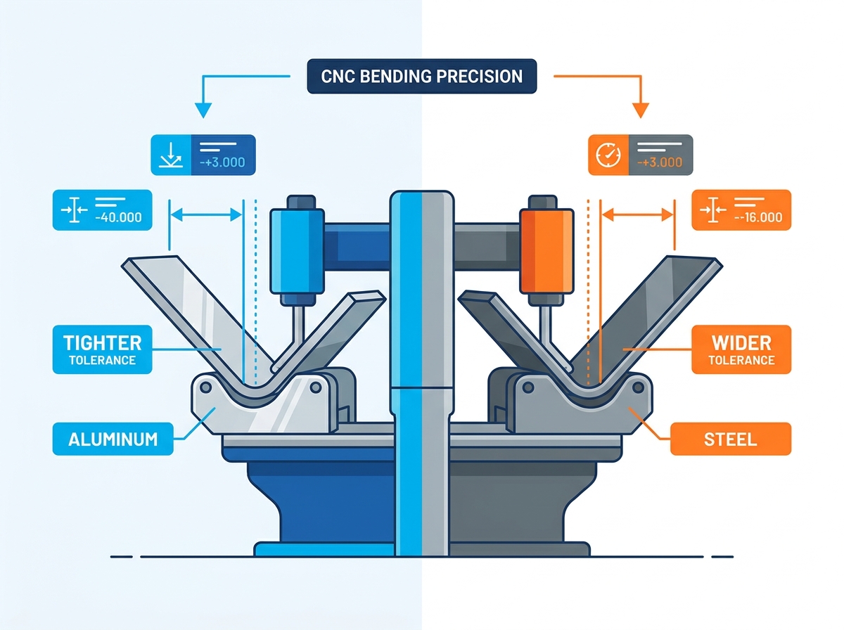
Achieving exact specifications is a multi-variable equation. Even with state-of-the-art machinery, several foundational factors dictate the final tolerances of bent components. Ignoring these variables during the design phase guarantees assembly headaches later.
Sheet metal is purchased from mills based on nominal gauges, but actual thickness varies within an acceptable mill tolerance. A sheet of 11-gauge steel might vary by ±0.005 inches across a single batch. In air bending, the depth of the punch penetration directly determines the angle. If the material is slightly thicker than the CNC controller assumes, the punch will drive deeper relative to the material neutral axis, resulting in an over-bent angle.
Sheet metal is manufactured by rolling it through massive cylinders. This process elongates the crystalline structure and creates a visible grain. Bending perpendicular across the grain allows for tighter tolerances, sharper radii, and minimizes cracking. In contrast, bending parallel with the grain weakens the bend, drastically increases the likelihood of fracturing, and makes springback highly unpredictable.
The bending process relies entirely on the accuracy of the flat blank. If the initial flat pattern is cut using low-precision methods, dimensional errors will transfer directly to the bent part. High-precision Laser Cutting ensures that the overall length, width, and bend relief locations are accurate to within ±0.005 inches before the material ever touches the press brake. A poorly cut blank guarantees an out-of-tolerance bent flange.
The physical condition and geometry of the press brake tooling are critical. Worn or unground dies cause inconsistent friction and uneven bending forces. The chosen bending method also affects precision. Air bending is the most versatile, relying heavily on the CNC controller accuracy. Coining forces the punch completely into the material, eliminating springback and achieving extreme precision, but it requires massive tonnage that can damage modern equipment.
Modern CNC press brakes feature hydraulic crowning systems that compensate for the microscopic bowing of the machine bed under heavy loads. Without crowning, long bends will have a different angle in the center than at the edges. Active angle-measurement lasers scan the bend in real-time, allowing the software to adjust the punch depth dynamically to counteract batch-specific springback.
Achieving precise dimensional and angular tolerances is not solely the responsibility of the machine operator. The foundation of precision begins in the engineering department. Design for Manufacturability dictates that the geometric features of a part directly influence how the material behaves under immense pressure. By optimizing your CAD models before production begins, you eliminate common points of failure.
One of the most effective ways to maintain tight tolerances and reduce manufacturing costs is to standardize the inside bend radii across your entire part. Every time a press brake operator has to change the punch and die to accommodate a different bend radius, the setup process resets. This introduces a new opportunity for minor calibration errors.
Engineers should select a single inside bend radius that applies to all flanges on the part. Match it closely to the material thickness. By utilizing a uniform radius, the manufacturer can complete all Metal Forming operations in a single handling step. This consistency stabilizes the process, minimizing tolerance stacking and ensuring the initial machine calibration remains accurate throughout the production run.
When sheet metal is bent, the material undergoes severe physical stress. The outer surface goes into tension while the inner surface compresses. This creates a localized deformation zone along the bend line. If holes or cutouts are placed too close to this zone, the physical stress will pull and distort the features. Circular holes turn into ovals, throwing positional tolerances completely out of specification. A perfectly aligned chassis cover might suddenly fail to mate with its internal standoffs.
To prevent this distortion, observe safe distance rules. The edge of any hole or cutout must be placed at a minimum distance of 2.5 to 3 times the material thickness plus the inside bend radius away from the bend line.
| Material Thickness | Inside Bend Radius | Minimum Distance from Bend Line |
|---|---|---|
| 0.039 inches / 1.0 mm | 0.039 inches | 0.136 inches |
| 0.078 inches / 2.0 mm | 0.078 inches | 0.273 inches |
| 0.118 inches / 3.0 mm | 0.118 inches | 0.413 inches |
| 0.236 inches / 6.0 mm | 0.236 inches | 0.826 inches |
When a design requires bending a flange that does not extend across the entire length of the material edge, the adjacent unbent material restricts the folding action. If forced, the metal will tear or warp at the corners. This instantly ruins the dimensional tolerance of the flange and compromises the structural integrity of the part.
To solve this tearing issue, designers must incorporate relief cuts. These small notches are placed directly at the ends of the bend line. By adding a bend relief, you effectively separate the material being folded from the stationary metal. This allows the flange to bend cleanly without dragging or warping the surrounding surface. The width of the relief cut should be equal to or greater than the material thickness, and the depth should equal the material thickness plus the inside bend radius.
Executing tight tolerances on the factory floor requires rigorous quality control and deep metallurgical expertise. Top-tier manufacturers utilize a highly controlled ecosystem of software and machinery to eliminate guesswork.
The quality control process must be uncompromising. Leading facilities employ First Article Inspection protocols before authorizing a full production run. Quality assurance engineers use sophisticated measurement tools like Coordinate Measuring Machines and calibrated digital protractors to verify that the initial bent part meets every dimension specified in the drawing. When fabricating a critical medical device chassis, a deviation of just 0.010 inches can cause internal circuit boards to misalign. Machine parameters are immediately adjusted before mass production begins.
Furthermore, the integration of advanced CAD and CAM software is non-negotiable. Manufacturing engineers simulate the entire process digitally to calculate the precise K-factor. This ratio represents the location of the neutral axis within the material during a bend. Accurately determining the K-factor allows the software to calculate the exact bend deduction and bend allowance, ensuring the flat pattern is perfectly sized.
Finally, the importance of skilled press brake operators cannot be overstated. Mill-supplied sheet metal has microscopic variations in thickness and tensile strength from one batch to the next. A highly skilled operator identifies these batch variations and adjusts the machine crowning system to ensure the bend angle remains perfectly consistent from the center of the part to the outer edges.
For standard commercial production using air bending techniques, the generally accepted angle tolerance is ±1.0 degree. This tolerance accounts for normal variations in material thickness and minor springback fluctuations. When utilizing precision-ground tooling and thinner gauge materials, top manufacturers can achieve tighter angular tolerances reaching ±0.5 degrees. Maintaining a ±0.5-degree tolerance on exceptionally long parts requires advanced press brakes equipped with active angle-measuring lasers and dynamic crowning systems.
Yes, the accuracy of the pre-processing stage directly impacts the final bending results. The physical length of a bent flange is entirely dependent on the dimensions of the initial flat blank. If the laser cutting process produces a blank that is out of tolerance by ±0.015 inches, that dimensional error transfers directly to the bent part. Laser cutting also introduces a Heat-Affected Zone along the edges. If cutting parameters are not perfectly tuned, thermal stress causes micro-hardening on the edges, leading to unpredictable springback or cracking.
Aluminum is not inherently harder to bend than steel, but it presents a different set of physical challenges. Aluminum is softer and exhibits less springback than high-strength steel, which makes hitting target angles slightly more predictable in alloys like 5052-H32. However, aluminum is highly anisotropic and susceptible to cracking along the bend line in harder tempers like 6061-T6. Steel possesses much higher tensile strength and exhibits significant springback, requiring higher tonnage and intentional over-bending.
The most effective way to reduce costs is to avoid over-tolerancing your designs. Specifying a tight tolerance of ±0.005 inches on a flange that only serves as a basic structural cover unnecessarily increases manufacturing costs due to slower production speeds and higher scrap rates. Engineers should loosen tolerances on non-critical dimensions, strictly standardize all inside bend radii to minimize setup times, and design the part so that all bends run perpendicular to the material natural grain direction.
Material thickness directly dictates the punch penetration depth required to achieve a specific angle in air bending. Sheet metal from the mill always has a slight thickness tolerance. If a batch of steel runs 0.005 inches thicker than the nominal gauge programmed into the CNC controller, the punch will push deeper relative to the metal's actual neutral axis. This results in an over-bent angle. Precision manufacturers often micrometer-check material batches and adjust the controller parameters before bending.
As a general engineering rule, the minimum inside bend radius should be equal to the material thickness for mild steel and highly formable aluminum like 5052. For stainless steel, a radius of 1.5 times the thickness is safer. Pushing the radius tighter than the material thickness causes severe stretching on the outer face, increasing the risk of cracking and making springback highly erratic. Consistent, slightly larger radii stabilize the forming process and yield much tighter dimensional repeatability.
Achieving tight tolerances in CNC bending is an objective science requiring a deep understanding of material physics, precise machinery, and intelligent engineering. Whether you are forming 5052 aluminum or 304 stainless steel, recognizing how thickness, grain direction, and springback influence the final part is critical to successful product development.
By applying proven design principles—such as standardizing radii and utilizing precision laser-cut blanks—engineers can minimize tolerance stacking and ensure reliable, cost-effective manufacturing. Working with a capable manufacturing partner early in the design phase eliminates guesswork and streamlines production.
To ensure your next project meets these rigorous standards, explore our comprehensive manufacturing capabilities or review our specific sheet metal materials to match your exact structural and tolerance requirements.


