 注: 建议图片大小150px*50px
丨
English
注: 建议图片大小150px*50px Views: 0 Author: Site Editor Publish Time: 2026-08-02 Origin: Site


Poorly prepared CAD files create massive engineering bottlenecks on the manufacturing floor. When a 3D model ignores the physical realities of bending, cutting, and forming metal, it triggers excessive revision cycles. You waste time, scrap material, and delay lead times. A model might look flawless on your screen. However, it will fail on the press brake if you ignore real-world manufacturing assumptions. Standardizing your CAD preparation protocols bridges the gap between digital design and physical production. This guide provides a technical framework for optimizing your files for a seamless handoff. Proper preparation ensures precise quotes and rapid turnaround times in custom sheet metal fabrication. You will learn how to structure models, apply correct bend logic, and export the exact file formats fabricators need to keep the shop floor moving.
Design for Manufacturability (DFM) is Non-Negotiable: CAD files must incorporate real-world constraints, including minimum bend radii, material-specific K-factors, and accurate hole-to-edge distances.
Scale and Format Dictate Accuracy: All models must be designed at a strict 1:1 scale, with 3D models (STEP/IGES) accompanied by accurate 2D flat patterns (DXF/DWG) for laser cutting and punching.
Material Selection Drives CAD Logic: The physical properties of chosen sheet metal fabrication materials directly alter bend deductions, tooling requirements, and tolerance capabilities.
Direct CAM Integration: Properly structured CAD files feed directly into fabricators' CAM (Computer-Aided Manufacturing) and CNC nesting software, drastically reducing lead times and programming errors.
Consistency Prevents Revisions: Discrepancies between 3D models and 2D technical drawings are the leading cause of production delays; establishing a single source of truth is critical for rapid quoting and production.
A production-ready CAD file requires zero unfolding errors, clear tolerance callouts, and manufacturable geometry. Many engineers fall into the trap of the perfect model fallacy. They design zero-thickness walls, intersecting geometries, and unbendable features. These digital anomalies immediately halt custom sheet metal processing on the shop floor. Fabricators cannot bend metal through itself. They cannot stretch material beyond its physical yield strength. When a model contains a flange that folds back into the main body without a relief cut, the CAM software rejects it. The operator then has to stop the machine, flag the project manager, and send an RFI back to your engineering department.
Fabricators rely on a downstream CNC and CAM pipeline to translate your design into reality. Raw 3D data gets parsed by CAM software. This software handles flat-pattern nesting and toolpath generation for laser, waterjet, or plasma cutting. It also dictates press brake sequencing. If your CAD file lacks proper bend reliefs, the material will tear at the corners. If you size holes incorrectly, hardware will not fit after plating. Every CAD preparation step directly dictates a specific manufacturing outcome. Accurate bend relief prevents material tearing. Proper hole sizing ensures hardware fits post-plating. Clear flat patterns allow the nesting software to maximize material yield across a 4x8 sheet.
To bridge this gap, you must understand how the shop floor interprets your files. The laser cutter only sees 2D vectors. It follows the lines you provide. If you leave construction lines, center marks, or title block borders in your DXF export, the laser will attempt to cut them. This ruins the part. The press brake operator relies on your 3D model and PDF drawing to understand the bend sequence. If the 3D model shows a 90-degree bend but the PDF calls out 85 degrees, production stops. Consistency across all file formats is the only way to ensure a smooth manufacturing process.
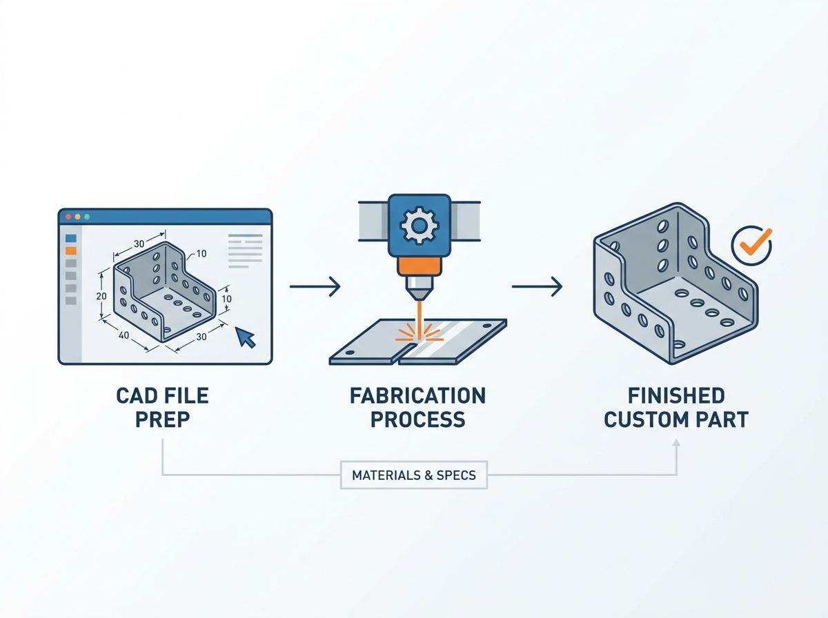
You must design at an absolute 1:1 scale. Scaling errors during CNC programming ruin entire production runs. Model your part in its final formed state. Ensure your software can successfully generate a flat pattern from this 3D model. Scaling artifacts often occur when exporting across different unit systems. Always verify your imperial or metric settings before exporting files for custom sheet metal parts. If you design a bracket in inches but export the STEP file in millimeters without proper conversion, the fabricator will receive a microscopic part. They will reject the file, costing you days in lead time.
When setting up your initial CAD workspace, define the material thickness globally. Do not manually extrude individual flanges to different thicknesses. Sheet metal comes in standard gauges. A single part cannot have a 0.060" flange and a 0.120" base unless it is a welded assembly. Use the dedicated sheet metal tools in your CAD software. These tools enforce uniform thickness rules and automatically apply bend radii based on your global settings.
The K-factor represents a mathematical reality. It calculates how the neutral axis shifts during bending. Material compresses on the inside and stretches on the outside. You must set bend deductions based on specific tooling, like the V-die width. Do not rely on default CAD software estimates. Include bend reliefs to prevent material deformation and tearing at the flanges. Validate your bend logic against physical forming data and manufacturer bend tables.
A common mistake is using a generic K-factor of 0.5 for everything. This assumes the neutral axis remains exactly in the center of the material. In reality, bending 5052 aluminum requires a different K-factor than bending 304 stainless steel. The tooling also changes the math. An air bend using a wide V-die produces a different bend allowance than bottoming out in a narrow die. If you do not know the exact tooling your fabricator will use, ask them for their standard bend deduction tables before you finalize your flat pattern.
| Material Type | Typical K-Factor Range | Minimum Bend Radius (Multiplier of Thickness) |
|---|---|---|
| Aluminum 5052-H32 | 0.40 - 0.45 | 1.5x to 2.0x |
| Stainless Steel 304 | 0.42 - 0.48 | 1.0x to 1.5x |
| Cold Rolled Steel (CRS) | 0.40 - 0.45 | 1.0x |
| Copper | 0.35 - 0.40 | 1.0x |
Material thickness dictates your minimum bend radius. Aluminum requires different bend parameters than stainless steel. The grain direction in specific materials impacts flat pattern orientation. It also affects the structural integrity of the final part. Coatings and plating change final hole dimensions. You must account for these dimensional shifts directly within your CAD file when selecting sheet metal fabrication materials.
If you specify a powder coat finish, remember that the coating adds thickness. A standard powder coat adds between 0.002" and 0.004" per surface. If you have a tight tolerance hole designed for a press-fit pin, the powder coat will make the hole too small. You must model the hole slightly oversized to accommodate the finish. Similarly, grain direction matters for materials like stainless steel or hard-tempered aluminum. Bending parallel to the grain increases the risk of cracking. Bending perpendicular to the grain yields a stronger part. You can indicate grain direction requirements on your 2D PDF drawing.
Self-clinching fasteners require strict placement rules. PEM nuts and studs need specific minimum edge distances. They must also match the material thickness compatibility. Model hardware holes using pre-punch dimensions rather than post-plating dimensions. Always run interference checks for hardware located close to bend lines. The press brake tooling needs physical clearance to form the flange without crushing the inserted hardware.
If you place a PEM nut too close to a bend, the V-die will hit the fastener during the forming process. The general rule is to keep the edge of the hardware hole at least 1.5 times the material thickness plus the bend radius away from the bend line. If you violate this rule, the fabricator will have to form the part first and manually install the hardware later using specialized anvil tooling, which increases labor costs.
Over-tolerancing drives up manufacturing costs unnecessarily. Standard commercial tolerances work for most applications. Tight tolerances require specialized setups and frequent quality checks. Tolerance stacking across multiple bends alters the final overall dimension of the part. Apply geometric dimensioning and tolerancing (GD&T) specifically tailored for sheet metal constraints.
A standard sheet metal tolerance is typically +/- 0.010" for hole locations and +/- 0.015" for bent dimensions. If you apply a +/- 0.005" tolerance to a dimension that spans three different bends, you are setting the fabricator up for failure. Every bend introduces a slight variation. These variations stack up. Design your parts so that critical mating features are on the same flange whenever possible. This eliminates tolerance stacking between those specific features.
Design your parts to accommodate laser kerf and CNC punch tooling limitations. Avoid sharp internal corners that require specialized punch tools. Keep minimum hole diameters relative to the material thickness. A 1:1 ratio serves as a safe baseline. Introduce tab-and-slot alignment features within your CAD model. These features aid self-fixturing during welding and assembly. They eliminate the need for expensive custom jigs.
When designing for a CNC punch press, remember that the machine uses physical tools to nibble away material. If you design an internal cutout with a sharp 90-degree corner, the punch tool will leave a small radius based on the tool's geometry. If you absolutely need a sharp corner for clearance, design a small "dog bone" relief into the corner. This allows the mating part to slide in without interference. For laser cutting, the kerf width is usually around 0.006" to 0.008". The CAM software compensates for this, but you should avoid designing features narrower than the material thickness, as the heat from the laser will melt the feature.
Parametric giants like SolidWorks, CATIA, and Autodesk Inventor offer dedicated sheet metal modules. These tools handle complex unfolding algorithms effortlessly. Mid-tier programs like Fusion 360 provide accessible alternatives with solid constraints. Non-parametric vector design programs like Adobe Illustrator lack physical sheet metal intelligence. They do not understand K-factors, material thickness, or bend allowances. Avoid using them for mechanical design.
Using the right software ensures your flat patterns are mathematically accurate. SolidWorks, for example, allows you to define a specific gauge table. This table links material thickness directly to the correct bend radius and K-factor. When you change the material in the software, the flat pattern updates automatically. Vector programs cannot do this. If you draw a flat pattern in Illustrator, you are just drawing lines. The fabricator will have to redraw the entire part in their CAD system to ensure it bends correctly, which adds engineering fees to your quote.
Utilize built-in collision detection and sheet metal interference checks before file submission. Tools like the SolidWorks Sheet Metal Check validate geometry instantly. Run automated system checks to detect overlapping flanges. Identify co-planar faces and invalid sheet thicknesses. Catching these errors digitally prevents scrap on the shop floor.
Always run a visual check of the flat pattern. Look for areas where flanges intersect. If two flanges overlap in the flat state, the part is physically impossible to manufacture from a single sheet of metal. You will need to adjust the flange lengths or add corner reliefs. Most parametric CAD software will flag this error automatically, but a manual review is always necessary before exporting files.
Fabricators require specific file formats to program their machines efficiently. Providing the correct files speeds up quoting and production. You must establish a standardized export routine to ensure consistency across all your projects.
| File Type | Format | Primary Use Case |
|---|---|---|
| 3D Model | STEP (.stp) / IGES (.igs) | Provides the universal 3D geometry. Avoids native proprietary version conflicts. |
| 2D Flat Pattern | DXF / DWG | Feeds directly into CNC nesting software. Must be clean of construction lines. |
| Technical Drawing | Acts as the legal contract. Details critical dimensions, tolerances, and finishes. |
Maintain strict layer hygiene for DXF files. Separate outer profiles and internal cutouts from bend lines. Place etching or marking text on distinct CAD layers. Remove title blocks, centerlines, and spline curves from the flat pattern. These elements confuse CNC nesting software. Your accompanying PDF must detail finish requirements, hardware specs, and bend angles.
Follow these steps when exporting your DXF flat patterns:
Flatten the sheet metal part in your CAD software.
Hide all sketches, planes, and construction geometry.
Export the face of the flat pattern directly to DXF.
Open the DXF in a 2D viewer to verify only the cut profile and bend lines remain.
Ensure the scale is exactly 1:1.
Sending a 3D model that contradicts the dimensioned 2D PDF guarantees a rejected quote. Fabricators do not know which file represents the true design intent. Establish a strict version control process. Implement a pre-submission review protocol to ensure total alignment between your 3D geometry and 2D documentation.
This conflict usually happens when an engineer updates the 3D model but forgets to rebuild and save the associated 2D drawing. The fabricator imports the STEP file into their CAM software and notices the overall length is 10 inches. They look at the PDF drawing, and it says 12 inches. Production stops immediately. To mitigate this, always package your files together in a single revision-controlled folder. If you change the model, generate a new PDF immediately.
Submitting models with overlapping flanges prevents the fabricator's software from unfolding the part. Deformed geometry creates the same roadblock. Mandate a test unfold within your native CAD software before exporting any files. If your software cannot flatten the part, the press brake cannot form it.
Another common unfolding error occurs when engineers use standard solid modeling features like fillets or chamfers on sheet metal edges before converting the part to sheet metal. The software gets confused by the complex edge geometry and fails to generate the flat pattern. Always build your parts using dedicated sheet metal features from the start. Add edge treatments like chamfers only after the base sheet metal logic is established.
Audit your current CAD files against standard DFM rules to ensure manufacturability.
Export clean STEP files and layered DXF flat patterns to streamline the quoting process.
Generate a comprehensive PDF drawing that clearly calls out tolerances, hardware, and finish requirements.
Submit your verified design package to a fabricator for a technical review and production quote.
A: The optimal formats are STEP (.stp) files for universal 3D modeling and clean DXF files for 2D flat patterns. These formats integrate seamlessly with fabricators' CAM software.
A: Fabricators can generate flat patterns from an accurate 3D model. However, providing a clean DXF speeds up the quoting and CNC programming process significantly.
A: The K-factor depends on the material type, thickness, and the fabricator's specific press brake tooling. Use standard industry charts as a baseline or consult your fabricator directly.
A: Models usually fail to unfold due to intersecting geometry, missing bend reliefs, or zero-thickness walls. Ensure all bends have appropriate radii and reliefs applied.
A: Yes, include them for visual reference and interference checking. Clearly call out the specific part numbers and pre-punch hole sizes on your accompanying 2D PDF drawing.
A: A standard rule of thumb is to make the minimum bend radius equal to the material thickness. Exceptions exist based on specific material tempers and tooling setups.
A: No. Vector programs lack physical sheet metal intelligence. They cannot calculate K-factors, bend allowances, or material thickness, making them unsuitable for mechanical design and custom fabrication FAQ references.


