 注: 建议图片大小150px*50px

丨
English
注: 建议图片大小150px*50px Views: 0 Author: Site Editor Publish Time: 2026-10-07 Origin: Site


A single millimeter of warping can completely scrap a complex metal enclosure. In the shop-floor reality, intense welding heat triggers rapid thermal expansion. Severe distortion often follows this thermal shock, easily destroying thin metal parts during the manufacturing process. Controlling this dimensional shifting is never a matter of luck. Rather, it is a highly regulated science involving meticulous preparation, specialized techniques, and advanced thermal management.
In this comprehensive engineering guide, we will explore exactly how industry professionals control deformation. From initial CAD preparation and shop-floor fixturing to advanced heat control and post-weld corrections, you will learn the practical methodologies required to maintain absolute precision in your fabrication projects.
Heat Input is the Primary Variable: The fundamental cause of welding deformation is excessive and uneven heat application. Controlling thermal input remains the absolute baseline for maintaining dimensional accuracy.
Preparation Dictates the Outcome: Proper joint design, accurate material selection, and the utilization of heavy-duty fixturing tables prevent warping before the arc is ever struck.
Technique Mitigates Stress: Advanced shop-floor methods like stitch welding, backstepping, and precise heat management allow fabricators to minimize heat-affected zones in thin-gauge materials.
Tooling is Essential: Relying on standard C-clamps is insufficient. Heat sinks, copper backing bars, and custom machined jigs are mandatory for maintaining strict tolerances during the thermal cycle.
To effectively control distortion, engineers and fabricators must first understand the underlying physics causing metal to change shape during the joining process. Deformation is not a random occurrence. Conversely, it is a direct mechanical response to severe temperature fluctuations.
Imagine applying a localized 6,000°F heat source to a cold steel plate. When heat from a welding torch touches the metal, the material in the immediate weld zone undergoes rapid thermal expansion. The surrounding cold, rigid metal resists this expansion, causing the heated area to yield and compress into itself.
As the heat source is removed and the glowing weld pool begins to cool, the metal naturally attempts to contract. However, because the surrounding material remains stiff, this contraction creates immense residual tensile stress. In thin sheet metal, the structural integrity of the material is often insufficient to resist these pulling forces. Consequently, the physical release of this locked-in stress manifests as buckling, twisting, or bowing across the entire component.
Material thickness plays a critical role in deformation. Thinner materials lack the cross-sectional rigidity to resist shrinkage forces, making them exponentially more susceptible to distortion than thick plates. Furthermore, the specific metallurgical properties of the chosen alloy dictate exactly how it will react to thermal shock.
Two primary factors determine a material's propensity to warp. The first is thermal conductivity, which dictates how fast heat moves through the metal. The second is the coefficient of thermal expansion, which measures how much the metal grows when heated.
| Material Type | Thermal Conductivity | Thermal Expansion Rate | Susceptibility to Warping in Thin Gauges |
|---|---|---|---|
| Carbon Steel (e.g., SPCC, Q235) | Moderate | Moderate | Moderate. Heat dissipates relatively well, and expansion remains predictable under standard clamping. |
| Stainless Steel (e.g., 304, 316L) | Low. Retains heat in the weld zone. | High. Expands up to 50 percent more than carbon steel. | Very High. Requires strict heat management, copper backing, and specialized cooling tooling. |
| Aluminum (e.g., 5052, 6061) | Very High. Heat spreads rapidly across the part. | Very High. Leading to significant expansion. | High. Rapid heat spread requires high initial amperage but extremely fast travel speeds to prevent warping. |
Deformation presents itself in several distinct mechanical ways. The specific type of warping depends heavily on where the weld is placed and how the part is physically constrained on the table.
Longitudinal Shrinkage: The weld metal contracts parallel to the weld line, causing the entire part to bow lengthwise like a banana.
Transverse Shrinkage: The weld metal contracts perpendicular to the weld line, pulling the two base plates closer together and altering overall width dimensions.
Angular Distortion: Uneven heating through the thickness of the metal causes the plates to fold toward the heat source, altering the planned angle of the joint.
Bowing and Buckling: Common in thin panels, residual compressive stresses push the metal outward, creating a wavy or domed surface.
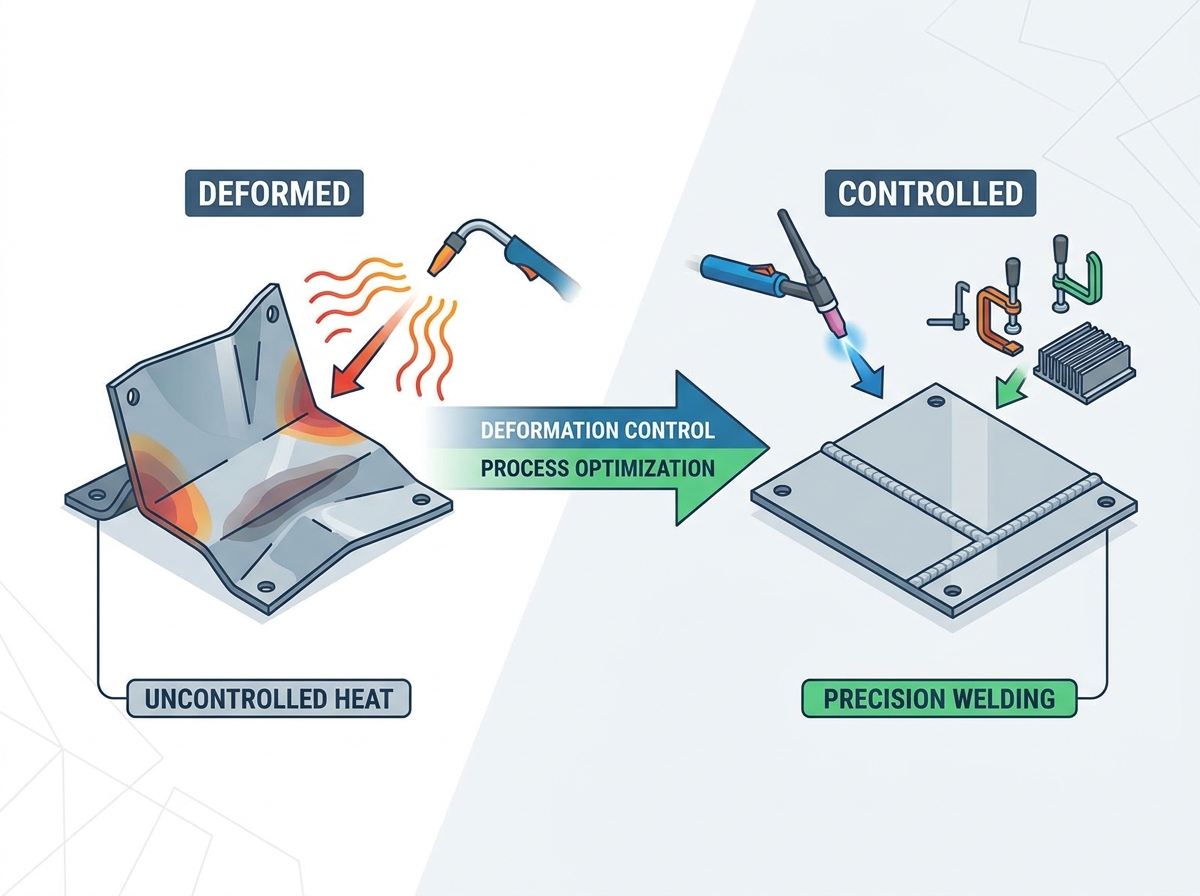
Deformation control does not begin on the shop floor. Rather, it starts in the engineering department. Decisions made during the CAD design phase directly impact how much residual stress will be introduced into the final component.
The placement of a weld joint significantly influences the mechanical leverage that shrinkage forces have on the part. When engineering welded structural parts, placing the weld as close to the neutral axis, or the center of gravity, of the component is highly recommended.
Welds placed symmetrically around the neutral axis allow shrinkage forces to balance each other out naturally. If a weld is placed far off-center, the contraction will act as a lever, pulling the entire structure out of alignment. Engineers must also consider joint types. For instance, a double-V preparation requires welding on both sides, which naturally balances the thermal stress compared to a heavy single-sided weld.
A frequent error in metal fabrication is over-welding. Welders or engineers sometimes specify a larger weld bead than structurally necessary, operating under the flawed assumption that bigger always means stronger. However, in precision manufacturing, the rule is almost always that less is more.
The volume of weld metal deposited is directly proportional to the amount of heat input and the resulting shrinkage force. If a 3mm fillet weld meets the mechanical load requirements, increasing it to a 5mm weld does not add proportional strength. Instead, it dramatically increases the heat-affected zone and the likelihood of warping. Engineering specifications should always dictate the minimum viable weld size to minimize thermal input.
Even with flawless design, the physical execution of joining thin metals requires rigid external support. Without proper mechanical restraint, thermal forces will freely distort the metal beyond repair.
Precision fabrication relies heavily on heavy-duty, cast-iron welding tables. These tables are machined perfectly flat and feature a precise grid of holes for modular clamping. Operators often lock down components using toggle clamps and heavy-duty squares machined to perfect 90-degree angles, creating a rigid, unyielding skeleton for the metal parts.
For high-volume or highly complex parts, custom jigs are machined. These fixtures force the metal to hold its exact geometric shape while hot. The part must remain clamped not just during the active joining process, but crucially, during the cooling cycle. Releasing clamps while the metal is still hot allows residual stresses to instantly warp the part.
To actively combat distortion, fabricators must remove heat from the weld zone as rapidly as possible. This is achieved through the strategic use of heat sinks.
Copper and aluminum are highly thermally conductive. By clamping copper backing bars directly behind the weld seam, the copper rapidly absorbs and pulls the excess heat away from the thin base metal. Because copper does not bond with steel or aluminum during the welding process, it acts as a safe and highly effective thermal sponge. This restricts the heat-affected zone and prevents the thermal expansion that leads to buckling.
Before any continuous beads are laid down, the entire component must be tacked together. Tack welds are small, intermittent, and temporary welds used to hold the assembly in strict alignment.
Strategic tacking locks the dimensions in place. If a fabricator attempts to weld a long seam without sufficient tacks, transverse shrinkage will cause the gap ahead of the torch to either snap shut or spread wide open. Placing small, evenly spaced tacks ensures the sheet metal assembly maintains tight ±0.1mm tolerances before the primary heat is introduced.
Once the part is designed correctly and clamped rigidly, the responsibility shifts entirely to the operator. The specific techniques used to apply the filler metal and heat dictate the final dimensional accuracy of the component.
A continuous, unbroken weld bead introduces a massive, uninterrupted line of heat into the metal. To prevent this thermal overload, fabricators frequently utilize stitch welding.
Stitch welding involves leaving predefined gaps between short welds, such as welding for two inches, leaving a two-inch gap, and repeating the cycle. This drastically reduces the total heat input introduced into the part. For many applications, an intermittent weld provides more than enough structural strength while keeping the base material well below the temperature threshold that causes severe warping.
When a continuous seam is structurally required, fabricators use the backstep technique to manage thermal buildup along the joint.
In standard welding, the operator moves linearly from point A to point B, pushing a wave of heat ahead of the torch. In backstepping, the overall progression might be from left to right, but each individual short weld is made from right to left. The operator starts a few inches ahead, welds backward into the previous bead, and then moves ahead again. This breaks the heat input into isolated zones, preventing the cumulative thermal expansion that causes longitudinal bowing.
Beyond physical tools and sequencing, the actual joining process selected plays a massive role in deformation control. For materials thinner than 3mm, Gas Tungsten Arc Welding is widely considered the gold standard.
Watching a skilled operator manipulate the foot pedal to feather the arc highlights why TIG welding is superior for delicate work. Unlike wire-feed processes that output a constant voltage, TIG allows the welder to manually adjust the electrical amperage in real-time. This pinpoint control means the operator can melt the base material with the exact amount of energy needed, drastically shrinking the heat-affected zone.
While MIG welding is significantly faster and great for thick structural steel, it can easily overwhelm thin sheet metal, leading to burn-through and severe warping. TIG is a slower, more deliberate process. By feeding the filler rod manually and controlling the puddle with precision, the overall thermal saturation of the base metal is kept to an absolute minimum.
As manufacturing tolerances become tighter across the aerospace, medical, and electronics sectors, the fabrication industry is rapidly shifting toward technology-driven solutions to mitigate welding distortion before a single arc is struck.
One of the most significant trends is the adoption of predictive thermal simulation software. Advanced Finite Element Analysis programs now allow engineers to virtually weld a component in a 3D digital twin environment. These algorithms calculate heat dissipation, predict exactly where the metal will warp, and suggest optimal clamping locations and weld sequences. By solving distortion issues digitally, manufacturers are drastically reducing physical prototyping costs.
Furthermore, the integration of automated robotic laser welding is revolutionizing thin-gauge fabrication. Unlike traditional arc welding, laser welding uses a highly concentrated beam of light to fuse metals. This process is incredibly fast and produces a heat-affected zone that is a fraction of the size of traditional methods. As laser technology becomes more accessible, it is quickly becoming the preferred method for high-volume enclosures where zero-distortion is a strict requirement.
When manufacturing complex components, engineers rarely deal with flat, two-dimensional plates. Most functional enclosures, brackets, and chassis involve multiple bends, flanges, and intersecting planes, making thermal management exponentially more difficult.
Every time a piece of metal is formed on a CNC press brake, mechanical stress is introduced into the material. The outer radius of the bend experiences tensile stress that stretches the material, while the inner radius experiences compressive stress that crushes it. These stresses remain locked inside the material at room temperature.
When welding operations are subsequently performed near these bent areas, the intense heat of the electrical arc drastically lowers the yield strength of the surrounding metal. As the metal softens, the localized mechanical stresses created during the bending process are suddenly released. This phenomenon, combined with the natural thermal expansion and contraction of the weld pool, creates cumulative stress. If not properly managed, this dual-stress environment will cause the entire part to twist out of tolerance.
Even when fabricators utilize optimal joint designs, advanced heat sinks, and strict sequencing, the fundamental laws of thermodynamics dictate that some residual stress will remain in the metal. For applications requiring extreme precision, these microscopic locked-in stresses are unacceptable and must be removed.
Thermal stress relieving is the most scientifically reliable method for eliminating locked-in welding stresses. This process involves placing the entire welded component into a highly calibrated industrial oven and slowly raising the temperature to a specific point below the metal's critical transformation phase.
For example, carbon steel assemblies are typically heated to between 1,100°F and 1,200°F, held at that temperature for one hour per inch of thickness, and then cooled down at a strictly controlled rate. This thermal soaking allows the metallic crystal lattice to relax and realign, permanently erasing the localized tension caused by rapid heating and cooling.
For components where thermal stress relieving is not viable, mechanical correction methods are employed. One highly effective technique is peening. Peening involves systematically striking the weld bead and the adjacent heat-affected zone with a specialized pneumatic hammer while the metal is still relatively warm. Because the weld metal naturally shrinks as it cools, it pulls on the surrounding base material. The mechanical impact of peening physically stretches the weld bead, counteracting the natural contraction forces.
Controlling deformation is a holistic manufacturing philosophy spanning from the initial CAD file to the final quality inspection. For procurement managers and lead engineers, selecting the right fabrication parameters is a critical business decision that directly impacts product viability.
If your project requires ±0.05mm dimensional tolerances on 1.2mm 304 stainless steel, standard MIG welding without specialized tooling will result in a 100 percent failure rate. In such scenarios, specifying TIG welding or automated laser welding, combined with custom copper heat sinks and post-weld precision grinding, is mandatory. Conversely, for a 5mm carbon steel bracket where a ±1.0mm tolerance is acceptable, standard MIG welding with symmetrical sequencing provides a cost-effective and structurally sound solution.
A fully integrated facility utilizes a closed-loop feedback system. If a welder notices that a specific joint configuration is prone to excessive transverse shrinkage, they can immediately consult with the in-house design engineers to modify the bend radius or joint geometry on the next production run. This seamless integration from laser cutting and CNC bending to precision welding ensures the highest quality output.
Controlling welding deformation requires a blend of smart engineering design, rigid fixturing, and deep metallurgical understanding. By implementing low-heat methods, strict assembly sequencing, and proper post-weld care, manufacturers can ensure flat, accurate dimensions every time.
In precision manufacturing, there is simply no room for error. Preventing distortion at the source saves invaluable time, reduces material waste, and lowers overall production costs. When tolerances matter, trusting the process to experienced professionals equipped with the right technology makes all the difference. To ensure your next complex project meets exact specifications without the risk of thermal distortion, explore the advanced manufacturing capabilities at DN CNC Sheet Metal today.
For precision applications involving thin sheet metal, TIG welding, also known as Gas Tungsten Arc Welding, is universally recognized as the superior manual method. Unlike continuous wire-feed processes, TIG utilizes a non-consumable tungsten electrode and allows the operator to manually control the electrical amperage via a foot pedal. This provides pinpoint control over the heat input, allowing the welder to melt the base material without introducing excessive thermal energy. This precise regulation is critical for preventing burn-through and minimizing the heat-affected zone.
Yes, a warped assembly can be corrected, but the process is highly labor-intensive and challenging. Minor distortion can be mitigated through mechanical straightening, which involves using hydraulic presses or planishing hammers to physically stretch the contracted metal back into shape. Alternatively, thermal shrinking can be applied, where localized heat is introduced to specific areas to force the metal to pull itself flat as it cools. Implementing strict heat control protocols to prevent distortion in the first place is always the most cost-effective approach.
Heat sinks are physical tools engineered to manage thermal transfer during fabrication. Typically machined from highly conductive materials such as copper or thick aluminum, these solid blocks are clamped tightly against the back or sides of the joint being welded. Because copper conducts heat significantly faster than steel or stainless steel, the heat sink rapidly draws the excess thermal energy out of the weld zone. By acting as a thermal vacuum, the heat sink prevents the high temperatures from migrating deep into the surrounding thin sheet metal.
Acceptable tolerances vary heavily based on the industry and application. For general commercial enclosures, a tolerance of ±0.5mm to ±1.0mm is often standard. However, in precision aerospace, medical device chassis, or highly integrated electronic enclosures, engineers frequently demand tolerances as tight as ±0.05mm to ±0.1mm. Achieving these micro-tolerances requires advanced fixturing, laser welding, and strict thermal management protocols.
Laser welding is vastly superior to TIG welding when it comes to minimizing distortion in thin sheet metal. While TIG provides excellent manual control, it still relies on a relatively wide electrical arc that spreads heat into the surrounding metal. Laser welding utilizes a highly focused, high-energy beam of light that melts the joint almost instantly. This results in a microscopic heat-affected zone, incredibly fast travel speeds, and virtually zero thermal distortion, making it ideal for high-precision, high-volume manufacturing.


