 注: 建议图片大小150px*50px
丨
English
注: 建议图片大小150px*50px Views: 0 Author: Site Editor Publish Time: 2026-08-04 Origin: Site


The 1-10-100 rule in manufacturing dictates a harsh reality: a design flaw that costs $1 to fix at the concept stage will cost $10 to correct during prototyping, and $100 if discovered during production. In sheet metal processing, delaying Design for Manufacturability (DFM) reviews routinely causes unmanufacturable geometries, excessive scrap, tooling delays, and severe schedule overruns. Friction often builds between design engineering teams focused on function and fabrication teams dealing with physical constraints on the shop floor.
To ensure a seamless transition from digital CAD to physical part, DFM protocols must be integrated at specific, early milestones in the project lifecycle. Waiting until the design is finalized before considering how the part will be cut, bent, and assembled guarantees inefficiency. By shifting the DFM review earlier in the timeline, engineering and manufacturing teams can align on material limits, tooling availability, and process capabilities before costly mistakes are locked in.
DFM review should ideally commence during the preliminary 3D CAD modeling phase, prior to finalizing material selection and geometric tolerances.
Process-specific constraints—particularly for laser cutting and CNC bending—must dictate design parameters, not the other way around.
Early collaboration with a manufacturing partner mitigates supply chain risks associated with specific sheet metal materials.
Automated DFM software and early vendor engagement are critical for scaling production across highly regulated sheet metal manufacturing industries.
A successful transition from design to production requires zero redesign loops, predictable unit economics, and strict adherence to lead times. When DFM is treated as an afterthought, these success criteria are rarely met. The sheet metal processing workflow relies heavily on sequential operations, meaning an error in the flat pattern cascades through cutting, bending, welding, and finishing.
Late-stage DFM incurs significant penalties. Discovering a flaw after the CAD model is finalized leads to expensive re-engineering, wasted prototyping cycles, and expedited tooling fees to fix unworkable geometries. Conversely, early-stage DFM ensures optimized material yield, maximizes standard tooling utilization, and accelerates time-to-market by eliminating the need for multiple design iterations.
| Project Phase | DFM Action Taken | Impact on Production | Scrap Risk |
|---|---|---|---|
| Concept / 3D CAD | Verify bend radii and standard gauges | High efficiency, standard tooling used | Low |
| Prototyping | Adjusting hole placements after failure | Moderate delays, rework required | Medium |
| Production | Discovering collision during CNC bending | Severe delays, custom tooling needed | High |
Custom tooling requirements drive up costs significantly when designs fail to conform to standard press brake punch and die geometries. Designing parts around common V-die widths eliminates custom tooling lead times and reduces setup costs. Engineers must design with standard tooling inventory in mind to maintain efficiency.
Identify the standard V-die widths available on the shop floor.
Calculate the minimum flange length required for each standard die.
Adjust CAD models to ensure all flanges meet or exceed this minimum length.
Standardize bend radii across the entire assembly to minimize tool changeovers.
Designs typically fail during the shop floor handoff due to impossible bend radii, inaccessible weld points, or conflicting tolerances. These failures stem from communication gaps between design engineers, who prioritize product function, and manufacturing engineers, who deal with fabrication realities. Bridging this gap early prevents production bottlenecks.
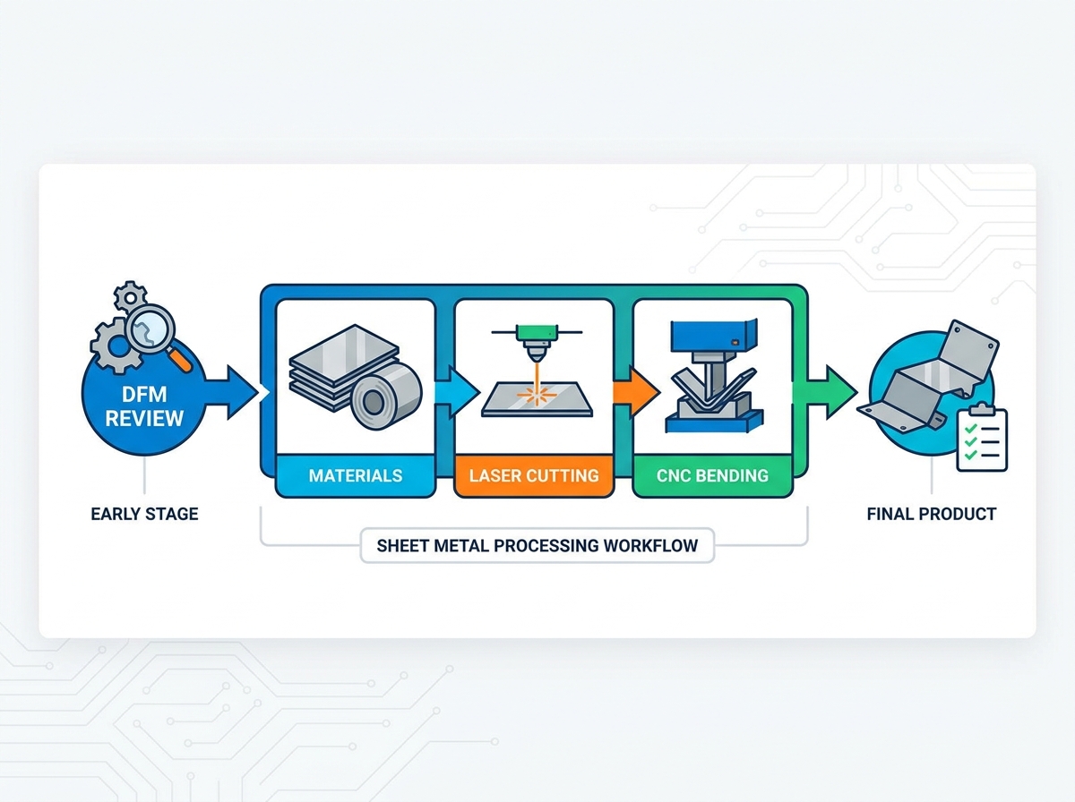
Conducting DFM requires a mix of in-house engineering review, automated CAD plugins, and contract manufacturer consultation. The timing of these reviews dictates their effectiveness on the shop floor.
DFM checks must initiate as soon as the base geometry is established in CAD. Modern CAD environments provide real-time manufacturability feedback, allowing engineers to unfold sheet metal parts to check for flat pattern collisions and verify true flange dimensions before the design progresses. Unfolding the model reveals overlapping flanges and tearing risks that are invisible in the folded 3D state.
Material selection dictates design limits. Designing with non-standard material thicknesses instead of industry-standard gauges increases costs and extends lead times. The tensile strength and thickness of specific materials alter required minimum bend radii and K-factor calculations. For example, Aluminum 5052 requires different bending parameters than Stainless Steel 304. Furthermore, parts must be designed considering grain direction; bending parallel to the rolling grain increases the risk of severe cracking or springback.
| Material Type | Standard Gauge Range | Recommended Min Bend Radius | Grain Direction Sensitivity |
|---|---|---|---|
| Aluminum 5052-H32 | 0.032" - 0.125" | 1.5x to 2x Thickness | High (Prone to cracking) |
| Stainless Steel 304 | 0.035" - 0.120" | 1x to 1.5x Thickness | Moderate (High springback) |
| Cold Rolled Steel (CRS) | 0.036" - 0.134" | 1x Thickness | Low |
Specific design features must map directly to the realities of primary fabrication processes. Ignoring the physics of the machinery leads to parts that look perfect on screen but fail in the machine.
Cutting paths must be reviewed early to account for technical constraints like kerf width, heat-affected zones (HAZ), and minimum hole diameter rules. For steel, a common rule is maintaining a 1:1 ratio between hole diameter and material thickness. Trade-offs between laser cutting and punching must also be evaluated regarding edge quality, micro-joints, and preparation for secondary finishing.
Bend geometries must be reviewed against standard press brake tooling inventory. Critical DFM checks include verifying minimum flange lengths, incorporating bend relief cutouts to prevent tearing, and adhering to hole-to-bend distance rules to prevent feature distortion. The choice between air bending and bottoming dictates achievable tolerances and necessary springback compensation.
DFM guidelines must cover post-cutting and bending operations. Designing self-fixturing features, such as tab-and-slot alignments, simplifies assembly, eliminates the need for expensive welding fixtures, and prevents distortion during fabrication.
A common late-stage failure is ignoring the thickness added by secondary finishes. Designers must adjust hole clearances, hinge spacing, and threaded fastener interfaces to accommodate plating, powder coating, or anodizing layers to ensure proper final assembly.
The timing and rigor of DFM change based on end-use application and production volume. Different sectors demand different levels of documentation and tolerance control.
Applying standard linear and angular tolerances, such as ISO 2768-m, early in the design process avoids over-tolerancing and reduces costs. Incorporating American Welding Society (AWS) standards for weld design and joint configurations ensures structural integrity and manufacturability.
DFM requirements differ significantly between low-volume prototypes, where manual workarounds are acceptable, and high-volume production, where automated, repeatable processes are mandatory. A critical milestone occurs when a design must pivot from low-volume laser cutting and bending to high-volume stamping or progressive die tooling.
Strict regulatory environments, such as aerospace and medical devices, require DFM reviews to be documented early. This ensures compliance with ISO standards, material traceability requirements (MTRs), and facilitates smooth first article inspections (FAI).
Ignoring DFM timing leads to severe consequences, requiring resilient processes to mitigate risks on the shop floor.
Poor DFM leads to inefficient nesting on sheet metal blanks, increasing material waste. Actionable mitigation strategies include standardizing sheet thicknesses across assemblies and designing parts to allow for optimal nesting margins.
Throwing the design over the wall to a manufacturer without prior consultation is highly risky. Vendor engagement should occur during the RFQ stage, requesting DFM feedback before a Purchase Order is issued. Leveraging a manufacturer's proprietary DFM software or engineering expertise identifies cost-saving design modifications early.
DFM review is not a final checkpoint but a continuous process that must begin during the initial 3D CAD modeling phase. Select manufacturing partners who provide automated DFM feedback alongside their quotes to ensure alignment from the start.
Audit your current design-to-manufacturing workflow to identify handoff bottlenecks.
Implement standardized DFM checklists for your engineering teams covering material, cutting, and bending constraints.
Upload your CAD files to your manufacturing partner early for an immediate manufacturability assessment.
Standardize your internal tooling library to match your fabrication partner's press brake inventory.
A: The most common mistake is ignoring minimum bend radius rules relative to material thickness, which leads to cracking or tooling failures during CNC bending.
A: Material selection impacts tooling requirements, bend allowances, and cutting speeds. Harder materials require larger bend radii and different laser cutting parameters compared to softer alloys.
A: The industry-standard formula dictates that the distance from the edge of a hole to the bend line should be at least 1.5 to 2 times the material thickness plus the bend radius to prevent distortion.
A: Laser cutting tolerances are generally tighter and operate in 2D space. CNC bending introduces 3D variables, including material thickness variations and springback, resulting in looser tolerances.
A: Bend relief cutouts prevent material tearing when bending a flange that does not extend the full length of the part, allowing the metal to deform cleanly.
A: A standard rule of thumb is to account for an extra 0.002" to 0.005" per surface to ensure adequate hole and thread clearance after powder coating or plating.


