 注: 建议图片大小150px*50px

丨
English
注: 建议图片大小150px*50px Views: 0 Author: Site Editor Publish Time: 2026-08-11 Origin: Site


The discrepancy between idealized CAD models and physical press brake realities is the leading cause of delayed production and cost overruns in sheet metal manufacturing. Engineers frequently design complex bends, tight tolerances, and intricate feature placements that are geometrically possible in software but physically impossible to form without deformation, tooling collisions, or material fracturing. Identifying which specific bend features require an early Design for Manufacturability (DFM) review prevents late-stage engineering changes. Catching these geometric conflicts before releasing drawings to the floor saves weeks of lead time and eliminates the need for rework. This guide breaks down the high-risk features that dictate whether a part can be efficiently processed by a CNC bending service without requiring custom tooling or secondary operations.
Feature Proximity is Critical: Holes, slots, and cutouts placed closer than four times the material thickness (4x *t*) to a bend line risk severe deformation without specialized tooling.
Material Dictates Geometry: Sheet metal material selection directly limits minimum bend radii and dictates springback compensation, requiring early alignment between design and shop-floor capabilities.
Relief Cuts Prevent Tearing: Adjacent bends and flanges require properly sized bend reliefs to prevent material tearing and ensure accurate forming.
Strategic Tolerancing Reduces Cost: Tightening only the tolerances strictly necessary for assembly prevents exponential cost increases and simplifies quality inspection.
Partner Evaluation: A competent CNC bending service should provide DFM feedback that bridges the gap between software simulation and actual tooling inventory before finalizing the quote.
A successful production run requires delivering parts that meet dimensional tolerances with zero scrap rates and minimal tooling setups. When engineering teams skip the initial DFM review, they introduce hidden variables into the production cycle. These variables manifest on the shop floor as unexpected material tearing, inconsistent bend angles, and rejected batches. Operators are forced to stop the press brake, write non-conformance reports, and wait for engineering to issue drawing revisions. Defining strict success criteria early ensures that both the design team and the manufacturing floor share the exact same quality expectations before the first sheet of metal is cut.
An early DFM review serves as a mandatory validation gate. It confirms whether sheet metal forming is actually the most viable method for the specific part geometry. Strict geometric constraints or extreme wall thickness requirements sometimes dictate alternative manufacturing processes. Validating the core manufacturing process before detailing the CAD model prevents engineers from forcing a sheet metal solution onto a part better suited for a mill or a casting facility. To properly screen a part for press brake forming, engineers must execute the following validation steps:
Verify uniform wall thickness across the entire part geometry to ensure compatibility with standard sheet stock.
Confirm that all internal radii match available standard tooling profiles to avoid custom die fabrication.
Assess the overall flat pattern size against the maximum bed length and tonnage capacity of the available press brakes.
Evaluate the necessity of secondary operations like welding or hardware insertion and ensure adequate clearances exist.
Check the design for enclosed profiles that might trap the tooling during the final bending sequence.
Modern 3D modeling software suffers from the infinite flexibility fallacy. CAD programs allow designers to place flanges, holes, and tight radii anywhere in digital space without physical resistance. The physical reality of a press brake operates under strict mechanical limits. V-dies, punches, and backgauges have physical mass and specific operational footprints. A gooseneck punch can only reach so deep into a return channel before colliding with the opposite flange. A standard V-die requires a specific amount of flat material to rest upon before the punch engages the metal. Ignoring these physical constraints guarantees manufacturing failure and forces operators to improvise dangerous or inefficient setups.
Unreviewed designs force manufacturers into difficult operational corners. When a part features non-standard radii or impossible flange lengths, the shop must purchase custom tooling or engineer complex, multi-stage setups. This inflates lead times and drives up the per-part cost. Applying DFM principles early simplifies machine programming and reduces the number of tool changes required per part. Parts designed with standard tooling in mind flow through the press brake seamlessly. Operators can utilize common air-bending setups, keeping cycle times low and production schedules on track while streamlining downstream quality inspection.
During the bending process, the material on the outside of the bend stretches while the inside compresses. The neutral axis shifts inward, creating a zone of severe plastic deformation. If a hole or slot sits too close to this deformation zone, the stretching forces will pull the feature out of round. A perfectly circular hole will warp into an oval, ruining assembly alignments and preventing hardware insertion.
The industry-standard baseline requires keeping holes and slots at least four times the material thickness (4x t) away from the start of the bend radius. If proximity is absolutely unavoidable due to tight packaging constraints, mitigation strategies exist. Manufacturers can punch or laser-cut the holes after bending using secondary operations, or utilize custom rotary dies that minimize surface dragging. These secondary operations always increase cycle times and require additional fixturing.
A flange must be long enough to span the V-die opening during the entire forming stroke. If the flange is too short, it will slip into the die before the bend is complete. This results in a ruined part, inaccurate bend angles, and potential damage to the press brake tooling. The required V-die width is typically determined by the material thickness, generally calculated at eight times the material thickness for standard mild steel air bending.
To calculate the minimum flange length, engineers must account for the die width and the material thickness. A reliable rule of thumb dictates that the minimum inside flange length should be at least 2.5 to 3 times the material thickness, plus the bend radius. Designing flanges shorter than this physical limit requires custom bottoming dies, specialized folding machines, or machining the feature from solid stock.
Hems fold sheet metal back onto itself to create a safe edge, increase structural stiffness, or improve cosmetic appearance. Evaluating the feasibility of flat hems versus teardrop or open hems is a mandatory DFM step. Flat hems require extreme tonnage to crush the material completely flat. This process works well for highly ductile materials like mild steel or 5052 aluminum but frequently causes harder materials to fracture along the bend line.
For harder alloys or thicker gauges, teardrop or open hems are required. The general rule for hemming dictates that the inside diameter of an open hem should equal the material thickness. The return length of the hem must be sufficient to prevent the edge from springing open or flattening out unevenly during the final pressing stage. Insufficient return lengths will slip out of the flattening die, creating a hazardous, unfinished edge.
Designing adjacent bends without adequate spacing creates massive stress concentrations. When two flanges meet at a corner, the material needs room to stretch and compress independently. Without proper separation, the metal will tear at the intersection, destroying the structural integrity of the part and creating sharp, jagged edges that fail safety inspections.
Bend reliefs solve this problem by physically separating the deforming metal from the flat metal. Properly sizing these reliefs is non-negotiable for shop floor success. The depth of a bend relief should equal the material thickness plus the bend radius. The width should be at least equal to the material thickness. Failing to include these specific cutouts in the flat pattern guarantees rejected parts and forces the laser operator to manually edit the cutting files.
Sharp internal corners in a flat pattern act as stress amplifiers. When the press brake applies tonnage to form the part, these sharp corners become the origin points for micro-fractures. Over time, or under dynamic load in the field, these fractures propagate and cause the component to fail catastrophically.
Adding proper corner radii to the flat pattern prior to bending distributes the stress evenly across the geometry. This simple DFM adjustment prevents stress concentrations and cracking during the forming process. It is a zero-cost design change that massively improves the fatigue life and durability of the final component without altering the functional assembly.
Self-clinching fasteners, such as PEM nuts, studs, and standoffs, are common in sheet metal assemblies. Evaluating their placement relative to bend lines ensures the part can actually be manufactured. If a fastener is installed before bending and sits too close to the V-die, the press brake tooling will crush the hardware or distort the surrounding metal during the downward stroke.
If the hardware is installed after bending, the hardware insertion press must have enough clearance to reach the hole without colliding with previously formed flanges. Ensuring adequate distance guarantees tooling clearance, prevents hole distortion, and ensures mating parts align perfectly during final assembly. Designers must check the specific footprint of the insertion anvil to verify clearance.
Common Bend Feature Constraints and DFM Guidelines
| Feature Type | Standard DFM Guideline | Risk of Non-Compliance |
|---|---|---|
| Holes & Slots | Distance from bend ≥ 4x material thickness | Severe feature distortion and elongation |
| Flange Length | Length ≥ 2.5x to 3x material thickness + radius | Material slips into V-die, failing to form |
| Bend Reliefs | Depth = thickness + radius; Width = thickness | Material tearing at adjacent bend intersections |
| Flat Hems | Avoid on high-yield or brittle materials | Cracking along the outside of the hem line |
| Hardware Proximity | Keep outside the V-die and insertion anvil footprint | Tooling collisions or fastener thread distortion |
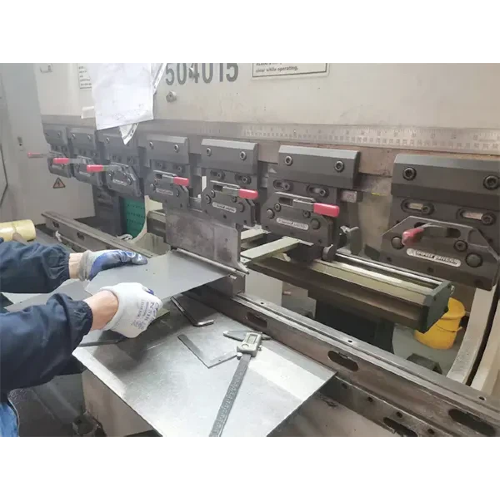
Proper sheet metal material selection dictates the entire bending strategy and tooling setup. Different alloys react to the stress of a press brake in vastly different ways. High-yield materials, such as 304 stainless steel or high-strength low-alloy (HSLA) steels, require significantly larger minimum bend radii compared to softer, more ductile alloys like 5052 aluminum. Forcing a tight radius on a high-yield material causes severe cracking on the outside tension face of the bend, compromising the part's structural integrity.
Springback predictability changes drastically across different alloys and tempers. Springback is the material's natural tendency to return slightly to its flat state after the punch releases its pressure. Harder materials exhibit greater springback, sometimes requiring up to 10 degrees of over-bending. Operators must calculate exact over-bending angles and select appropriate punches to compensate. Early DFM reviews identify these material-specific behaviors, allowing engineers to adjust their CAD models to reflect the true formed dimensions rather than theoretical perfection.
Sheet metal is manufactured by rolling large ingots through heavy rollers at the mill. This process creates a distinct grain direction within the metal, similar to the grain found in dimensional lumber. Understanding this grain direction is vital for maintaining structural integrity during the forming process, especially for thicker gauges and harder alloys.
Bending parallel to the material grain is highly risky. It separates the grain boundaries and frequently leads to fracturing or deep cracking along the bend axis. Bending perpendicular to the grain allows the material to stretch safely across the grain lines. DFM reviews optimize flat pattern nesting on the laser cutter or punch press to ensure critical bends run perpendicular to the grain. This careful planning balances maximum material yield on the sheet with uncompromising part integrity.
When assessing a manufacturing partner, determine if they rely solely on automated DFM software or if they apply practical, tooling-specific knowledge. Automated software is excellent for catching basic proximity errors and calculating standard bend deductions, but it cannot account for a specific shop's machine condition, tooling wear, or operator expertise.
A capable partner reviews flat patterns against actual machine constraints. They calculate press brake tonnage limits to ensure their machines can physically fold the chosen material at the specified length without exceeding the hydraulic capacity. They check for backgauge interference, ensuring the part can be safely gauged and supported during the bending stroke. Real-world shop floor experience prevents situations where a part passes software simulation but cannot be physically handled by the operator.
Evaluating a vendor's standard tooling library is a mandatory step in the quoting process. Every shop has a unique inventory of punches, V-dies, and gooseneck tools. If the design utilizes standard radii that match their existing inventory, the parts can be air-bent quickly and economically without additional tooling charges.
If the design requires non-standard radii, extreme tolerances, or complex offset bends, a strict cost-benefit analysis is required. The engineering team must decide whether to modify the design to fit standard air-bending tools or pay Non-Recurring Engineering (NRE) costs for custom bottoming or coining dies. A transparent manufacturer highlights these tooling conflicts during the DFM phase, providing the opportunity to design out unnecessary costs before production begins.
Tolerance accumulation is a harsh reality in parts featuring three or more sequential bends. Every time a press brake cycles, a tiny margin of error is introduced due to material thickness variations, springback inconsistencies, and machine positioning limits. When a part is dimensioned sequentially from one bend to the next, these small errors stack up. By the time the final bend is executed, the overall part dimension may be completely out of tolerance, rendering the part useless for assembly.
To mitigate this risk in bent sheet metal components, engineers must dimension critical features from a single, reliable datum edge. This strategy isolates the bending variations and prevents them from compounding across the part. Apply the principle of tightening only the tolerances absolutely needed for fit, form, and function. Over-tolerancing non-critical dimensions forces the manufacturer to slow down, perform excessive manual inspections, and discard functional parts, drastically inflating manufacturing costs.
The immense pressure required to fold metal inevitably leaves tooling marks. The material drags across the hard steel shoulders of the V-die, leaving visible scuffs, scratches, and indentations. For internal brackets or structural components, this is irrelevant. For cosmetically critical surfaces, such as front-facing enclosures, architectural panels, or consumer product housings, die marks are unacceptable and lead to immediate rejection.
Identifying this risk early allows the manufacturer to deploy specific mitigation tactics. Specifying the use of urethane dies or urethane protective films prevents metal-on-metal contact, eliminating die marks entirely. Engineers can also adjust the bend radii to reduce localized pressure on the die shoulders. These cosmetic protections must be established during the DFM review, as they require different tooling setups, alter the bend deduction calculations, and add setup time to the production run.
Early DFM review is a mandatory engineering gate that determines the technical and financial viability of sheet metal designs. By addressing hole proximity, flange limits, and material behaviors early, engineering teams eliminate the root causes of production delays and scrap. To ensure the next project moves smoothly from CAD to the shop floor, execute the following steps:
Export current sheet metal models, including both the flat patterns (DXF) and the folded 3D STEP files, to provide complete geometric data.
Audit all drawings to ensure holes and slots strictly adhere to the 4x material thickness proximity rule.
Verify that all internal corner radii and bend reliefs are explicitly modeled and sized according to the material thickness.
Submit finalized files to a qualified manufacturing partner for a comprehensive manufacturability audit before locking in the final assembly design.
A: To prevent deformation, holes and slots should generally be placed at a distance of at least four times the material thickness (4x t) plus the bend radius away from the bend line.
A: Bend reliefs are small cuts made adjacent to a bend to separate the material being deformed from the flat material, preventing tearing and distortion during the press brake operation.
A: Harder materials with higher yield strengths require larger minimum bend radii to prevent cracking on the outside of the bend, whereas softer, more ductile materials can accommodate tighter radii.
A: Springback is the tendency of sheet metal to partially return to its original flat shape after being bent. CNC press brakes must over-bend the material by a specific degree to compensate for this effect.
A: Applying unnecessarily tight tolerances to non-critical dimensions forces manufacturers to use specialized tooling, perform frequent manual inspections, and run slower cycle times, which significantly increases the per-part cost.
A: DFM reviews should be requested during the prototyping phase, before finalizing the assembly design. Modifying bend radii, hole placements, or flange lengths later in the process often requires costly redesigns of mating components.


