 注: 建议图片大小150px*50px
丨
English
注: 建议图片大小150px*50px Views: 0 Author: Site Editor Publish Time: 2026-08-05 Origin: Site


Intersecting bends dictate manufacturing yield on the shop floor. Unoptimized corners cause tearing, dimensional inaccuracy, and rejected assemblies in precision metal fabrication. Engineers face constant challenges managing localized stress concentrations, material flow, and tooling constraints when designing complex geometries. Poor corner specification inflates scrap rates and secondary processing requirements. Addressing these challenges requires a systematic approach to selecting and evaluating specific corner features. Implementing the correct bend reliefs, optimized radii, edge treatments, and joint configurations ensures structural integrity. This methodology guarantees manufacturability in advanced sheet metal forming. You must balance geometric requirements with material limits to produce high-quality components consistently.
Relief Geometry Dictates Yield: Specifying the correct bend relief (rectangular, tear-drop, or obround) prevents material tearing at flange intersections and accommodates tooling clearances.
Material Selection Constrains Design: The ductility, tensile strength, and grain orientation of specific sheet metal materials strictly dictate the minimum allowable internal corner radii and relief dimensions.
Process-Specific Tolerances: Corner feature selection must align with the intended manufacturing method (e.g., progressive die stamping vs. precision press braking) to avoid unexpected tooling costs and interference.
Secondary Operations Drive Cost: Designing self-locating or properly gapped open corners significantly reduces the labor hours required for downstream welding, grinding, and finishing.
Bending metal at intersecting planes introduces severe physical stresses. The material experiences extreme tension on the outside radius and intense compression on the inside radius. The neutral axis shifts toward the inside of the bend during deformation. These opposing forces converge at corner intersections, creating complex stress concentrations. If you do not manage these forces, the structural integrity of the entire component degrades rapidly. Operators see this daily when un-relieved corners snap during the press brake cycle.
Material displacement at corners creates significant deformation risks. When metal bends, it must flow somewhere. Without proper relief features, this displaced material causes bulging along the bend line. It can also lead to severe cracking or warping across the flange. Relieving this stress allows the metal to deform predictably without compromising the surrounding geometry. You have to give the metal a place to go, or it will force its own path and ruin the part.
Anisotropic behavior further complicates corner design. The rolling direction of the metal establishes a distinct grain structure at the mill. Bending parallel to this grain direction dramatically increases the risk of cracking. You must orient flat patterns so that critical bends cross the grain perpendicularly or at an angle. This orientation maximizes deformation limits and prevents premature failure at high-stress corners. Nesting software often ignores grain direction to save material, but this practice destroys parts with tight corner radii.
Different sheet metal materials respond uniquely to corner stress. Alloys like 5052-H32 aluminum offer high ductility but require larger bend radii to prevent surface fracturing. In contrast, 304 stainless steel work-hardens rapidly, demanding robust tooling and precise relief sizing. High-Strength Low-Alloy (HSLA) steel presents extreme yield strength, dictating strict minimum feature sizes to avoid tensile failure during forming. You cannot use the same corner relief dimensions for mild steel and aerospace-grade aluminum.
| Material Type | Typical Condition | Minimum Inside Radius (Multiplier of Thickness) | Corner Cracking Risk |
|---|---|---|---|
| Cold Rolled Steel (1018) | Annealed | 1.0 x T | Low |
| Aluminum 5052 | H32 Temper | 1.5 x T to 2.0 x T | Moderate |
| Aluminum 6061 | T6 Temper | 3.0 x T to 4.0 x T | High (Requires larger reliefs) |
| Stainless Steel 304 | Annealed | 1.0 x T to 1.5 x T | Moderate (Work hardens at corners) |
Engineers must evaluate several specific geometric features to optimize corner performance. These solution categories include bend reliefs, corner radii, chamfers, and joint types. Each feature plays a specific role in managing stress and accommodating manufacturing tooling on the shop floor.
Bend reliefs physically separate intersecting flanges to prevent tearing. You must evaluate rectangular, circular, obround, and tear-drop reliefs based on the application. Rectangular reliefs are common and easy to program, but they introduce stress risers at sharp internal corners. Circular and tear-drop reliefs distribute stress more evenly across a larger surface area. This makes them ideal for high-vibration environments where fatigue failure is a concern.
Standard sizing formulas ensure proper relief function. The relief depth must be greater than or equal to the material thickness plus the bend radius. The relief width must be at least equal to the material thickness. Adhering to these formulas prevents material from binding during the bending operation. If you undersize the relief, the press brake tooling will drag the adjacent flange, causing distortion.
The fabrication method impacts relief design. Laser-cut reliefs offer high precision and smooth edges, reducing stress concentrators. Punched reliefs may require micro-joints or specific tab designs to maintain sheet stability during processing. These choices directly affect tooling accessibility and the accuracy of flat pattern generation. A laser can cut a perfect tear-drop relief, while a turret punch might require multiple hits with a round tool to achieve a similar shape.
The internal bend radius must align with the material thickness and the available punch tip radius. Specifying a radius smaller than the punch tip forces the material to coin, increasing localized stress and requiring massive machine tonnage. You must maintain a precise relationship between these variables to ensure consistent angular accuracy. Air bending forms the radius based on the die V-opening, not just the punch tip.
Every material possesses a minimum bend radius threshold. This ratio prevents tensile failure on the outside of the bend. Harder tempers require a larger radius to accommodate the lack of ductility. Pushing beyond these limits guarantees cracking and part rejection. If a print calls for a sharp corner on 6061-T6 aluminum, the fabricator will have to reject the drawing or risk producing scrap.
Engineers must evaluate the structural trade-offs of corner radii. Sharp corners act as severe stress concentrators, weakening the overall assembly under load. Generous radii distribute loads effectively but may interfere with mating components. Coining operations create sharp internal corners but trap residual stress. Air bending allows for more natural material flow but requires larger tolerances for the final corner geometry.
Chamfered corners on flat patterns prevent material collision during folding. When two flanges meet at a 90-degree angle, the inside edges can interfere due to material thickness. A simple 45-degree chamfer removes this interference. This allows the flanges to close tightly without distortion or requiring the operator to force the fit with a mallet.
Fillets improve safety and performance. Rounding sharp external corners prevents injuries during manual handling and assembly. Fillets also enhance paint and coating adhesion. Liquids pull away from sharp edges due to surface tension, leaving corners exposed to rust. In dynamic applications, filleted corners significantly improve fatigue resistance by eliminating sharp points where cracks initiate.
Selecting the correct joint type depends on the final application of the formed sheet metal parts. Open corners provide excellent drainage and tolerance forgiveness. They also allow zinc plating and powder coating to penetrate fully, preventing hidden corrosion in outdoor environments.
Closed corners offer superior aesthetics and structural rigidity. Mitered joints provide a clean look, while butt and overlap joints offer easier alignment for welding. Properly designed closed corners are essential for enclosures requiring EMI/RFI shielding or environmental sealing. You must leave a slight gap (usually 0.010 to 0.030 inches) in closed corners to allow weld filler metal to penetrate the joint fully.
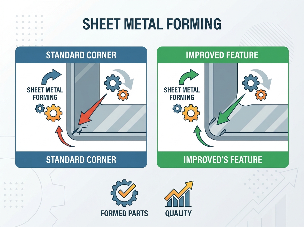
Corner feature selection must map directly to specific industry requirements and production environments. A design that works perfectly for a low-volume prototype may fail completely in a high-speed production run. Understanding these operational differences ensures successful manufacturing and prevents costly redesigns.
High-volume stamping differs vastly from precision press braking. Hard-tooled progressive stamping can coin or punch complex reliefs in a single stroke. This allows for intricate corner geometries without adding cycle time. Manual or CNC press braking requires standard punch and die clearances. You must plan bend sequences carefully to avoid tooling collision at complex corners. A deep box corner might require a specialized horn punch or window tooling to clear previously formed flanges.
Application-specific compliance drives corner specification across various industries. Consider how different sectors approach metal forming applications:
Aerospace & Defense: High-fatigue environments demand strict, non-sharp corner radiuses. Grain direction optimization is mandatory to prevent catastrophic failure under cyclic loading. Tear-drop reliefs are standard.
Sanitary & Food Grade: Stainless steel components require crevice-free transitions. Continuously welded and ground corners eliminate bacteria traps, ensuring compliance with strict hygiene standards. Open corners are strictly prohibited.
Electronics & NEMA/IP Enclosures: Precision closed corners are critical. These joints must accommodate gasketing to maintain liquid-tight seals and protect sensitive internal components from dust and moisture.
Heavy Equipment: Thick plate forming requires massive bend radii and large open corners to accommodate heavy weld beads. Tight tolerances are less critical than structural weld penetration.
| Joint Type | Tooling Complexity | Secondary Operations | Best Application |
|---|---|---|---|
| Open Corner | Low | Minimal (Deburring only) | Internal brackets, drainage components |
| Closed (Butt Joint) | Medium | Moderate (Tack welding) | Standard enclosures, structural frames |
| Fully Welded & Ground | High | Extensive (Welding, grinding, polishing) | Sanitary equipment, aesthetic fascias |
| Overlap Joint | Medium | Spot welding or riveting | HVAC ducting, lightweight panels |
Corner design directly impacts the total manufacturing cost of the part. Over-specifying tolerances or requiring non-standard features inflates production expenses. You must analyze how each geometric decision influences overall value and shop floor efficiency.
Tooling and setup costs represent a major financial factor. Specifying non-standard corner radii forces fabricators to purchase custom punch and die sets. Using standard house tooling eliminates these upfront costs and reduces setup time. Always consult your manufacturing partner's tooling library before finalizing corner dimensions. If you design a 0.125-inch radius but the shop only has 0.030-inch and 0.250-inch punches, you will face delays.
Secondary operations consume massive amounts of labor. Welding, grinding, and finishing are notoriously time-intensive. Improperly designed closed corners with large gaps require excessive weld filler. Grinding these heavy weld seams down to a smooth finish adds unnecessary hours to the production cycle. A well-designed corner that self-fixtures and leaves a tight, consistent gap allows a welder to run a fast, clean TIG bead without adding filler rod.
Material utilization and nesting efficiency also affect costs. Complex corner chamfers, intricate relief cutouts, and scrap ladders take up valuable space on the flat blank. This reduces the number of parts you can nest on a single sheet during laser cutting or punching. Poor nesting increases the per-part material cost and generates excessive scrap metal.
Moving a design from CAD to the shop floor introduces significant implementation risks. What looks perfect on a screen often fails during physical bending. Identifying these common failures early prevents costly rework and production delays.
Flat pattern calculation errors are a primary source of corner failure. Applying an incorrect K-factor or bend deduction leads to severe dimensional inaccuracies. These errors cause corner collisions, excessive gaps, or overall out-of-tolerance dimensions. Accurate flat pattern generation requires precise knowledge of the specific material batch and tooling setup. A K-factor of 0.33 for aluminum will not work for stainless steel, and using the wrong value will push the corner flanges out of alignment.
Springback causes corner angle distortion. When bending metal, it naturally attempts to return to its flat state. Unmanaged springback at complex multi-flange corners compromises the alignment of the entire assembly. Tool designers must compensate for this by over-bending the material slightly. This requires precise calculations and test bends. High-strength materials exhibit massive springback, making tight closed corners extremely difficult to achieve without specialized bottoming dies.
Prototyping and simulation mitigate these risks effectively. We recommend utilizing advanced Design for Manufacturability (DFM) software. Finite Element Analysis (FEA) and Forming Limit Diagrams (FLD) allow engineers to simulate material thinning and flow. Validating corner features digitally prior to production runs saves time, material, and frustration. Simulating the bend sequence ensures the part will not collide with the press brake ram or adjacent tooling during the final corner folds.
Audit your current flat patterns to identify missing or undersized bend reliefs that cause tearing.
Consult with your fabrication partner to align your designs with their specific DFM guidelines and available press brake tooling.
Standardize bend relief and radii tables within your engineering department to ensure consistency across all projects.
Implement simulation software for complex multi-flange parts to predict material flow and springback before cutting metal.
A: The standard bend relief depth should equal the material thickness plus the bend radius. The width should be at least equal to the material thickness. This sizing ensures the material does not tear or bind during the bending process.
A: Corners tear because intersecting flanges restrict natural material flow. Without a proper bend relief, the extreme tension on the outside radius exceeds the material's ultimate tensile strength, causing fractures at the intersection.
A: Thicker materials and harder tempers require larger minimum bend radii. Harder materials lack ductility, making them prone to cracking under tension. A larger radius distributes the bending stress over a wider area, preventing failure.
A: An open corner leaves a deliberate gap between flanges. A closed corner brings the flanges tight together without joining them. A welded corner fills the seam with metal, providing maximum structural rigidity and environmental sealing.
A: Corner chamfers remove excess material from the inside edges of intersecting flanges. This prevents the flanges from colliding and distorting as they are folded into their final 90-degree positions.
A: Bending parallel to the grain direction increases the risk of cracking. Orienting flat patterns so that bends run perpendicular or diagonal to the grain maximizes the material's deformation limits and improves corner quality.


