 注: 建议图片大小150px*50px

丨
English
注: 建议图片大小150px*50px Views: 0 Author: Site Editor Publish Time: 2026-08-08 Origin: Site


Manufacturing complex sheet metal components frequently exposes the limitations of standard fabrication routing. When you deal with multi-axis bends, tight tolerances, deep cavities, and mixed-material assemblies, standard methods fall short. Selecting incompatible processing methods or sequencing them incorrectly leads to compounding errors. You get material fatigue, heat distortion, high scrap rates, and assembly failures. A print might look perfect in a CAD environment, but it will fail at the press brake if the upstream cutting process introduces too much heat or hardens the material edges.
To mitigate production risks and control scrap, engineering teams must critically evaluate the end-to-end workflow. You need to align specific cutting, forming, machining, and joining techniques with the structural requirements of the final part. We see this on the shop floor every day. Success requires treating the entire fabrication cycle as a highly interdependent system rather than a series of isolated workstations.
Material dictates method: The physical properties of sheet metal materials (yield strength, grain direction, thermal conductivity) strictly limit which cutting and forming processes can be applied without compromising part integrity.
Upstream precision controls downstream success: Edge quality and thermal distortion introduced during initial cutting phases directly dictate the achievable accuracy of subsequent CNC bending and welding steps.
Hybrid manufacturing is often mandatory: Highly complex sheet metal parts frequently require secondary CNC machining or turning to achieve tolerances that standard sheet metal forming cannot produce.
Cold joining vs. thermal welding: For highly complex or thin-gauge parts, mechanical fastening (pressure riveting, hardware insertion) is often required to prevent the warping associated with traditional welding.
DFM is a mandatory processing step: Evaluating manufacturability and generating accurate blueprints before production begins is the only reliable way to identify impossible geometries and prevent costly late-stage redesigns.
Defining what elevates a part from standard to complex establishes the baseline for process selection. Complexity arises from intersecting bend lines, internal cutouts placed near bend radii, strict cosmetic requirements, non-standard material thicknesses, and hybrid features requiring multiple fabrication disciplines. These variables demand a higher degree of precision and control than simple brackets or flat panels. You cannot approach a multi-flange aerospace enclosure the same way you approach a basic HVAC duct.
Mapping the standard sheet metal processing workflow provides a framework for identifying potential failure points. While a linear progression works for basic parts, complex geometries force engineers to evaluate how downstream assembly requirements dictate specific upstream cutting and forming decisions. A standard shop floor routing sequence includes several distinct phases.
Blueprint Generation and CAD/CAM Translation
Primary Blanking and Profile Cutting
Deburring and Edge Preparation
Forming and CNC Bending
Secondary CNC Machining
Joining and Hardware Assembly
Surface Finishing and Final Inspection
The CAD-to-CAM translation represents a critical, frequently overlooked step. Finalizing drawings requires calculating precise K-factors, determining accurate bend allowances, and generating exact flat patterns before any metal is cut. The K-factor represents the ratio of the neutral axis to the material thickness. When you bend metal, the inside compresses and the outside stretches. Failing to account for this material stretch during the flat pattern generation guarantees dimensional failure during forming. Software simulations must validate the flat pattern against the physical properties of the chosen metal.
Complexity requires a non-linear evaluation dimension. For example, knowing a part requires a watertight TIG weld at the assembly stage forces the selection of a high-precision fiber laser during the blanking stage. This ensures a zero-gap tolerance at the weld seam. Every step heavily influences the viability of the next. Operators must measure the first article at each workstation to verify that the theoretical CAD dimensions match the physical reality of the metal.
The selection of sheet metal materials directly impacts processing viability and dictates the available fabrication methods. Analyzing features-to-outcomes reveals stark differences between common alloys. You cannot force a tight radius on certain metals without causing structural damage. For instance, 5052 aluminum offers excellent formability for tight radii, whereas 6061 aluminum is prone to cracking during bending unless processed in a specific temper or formed with generous radii. Similarly, 304 stainless steel work-hardens rapidly. It requires higher tonnage press brakes and specialized heavy-duty tooling compared to standard cold-rolled steel.
Grain direction plays a structural role in forming success. Sheet metal is rolled at the mill, creating a directional grain structure along the length of the sheet. Bending parallel to this grain significantly increases the risk of micro-fracturing and structural failure, particularly in harder alloys like stainless steel or tempered aluminum. Engineers must orient bend lines perpendicular to the material's grain direction during the nesting and blanking phase to preserve part integrity. If a complex part requires bends in multiple directions, you must nest the flat pattern at a 45-degree angle to the grain to distribute the stress evenly.
Thermal dynamics further complicate material selection. Highly conductive materials, such as copper or specific aluminum alloys, dissipate heat rapidly. This makes traditional laser cutting and welding difficult because the material pulls heat away from the cut zone or weld pool. Conversely, materials with high carbon content react aggressively to thermal cutting, creating brittle edges that complicate subsequent tapping or forming operations. Understanding these thermal behaviors necessitates specific processing workarounds, such as utilizing waterjet cutting for heat-sensitive alloys.
Material Selection Guidelines for Fabrication
| Alloy Grade | Yield Strength | Formability | Thermal Conductivity | Ideal Application |
|---|---|---|---|---|
| Aluminum 5052-H32 | 28,000 psi | Excellent | High | Complex enclosures, tight radius bends. |
| Aluminum 6061-T6 | 40,000 psi | Poor (Prone to cracking) | High | Structural brackets requiring high strength. |
| Stainless Steel 304 | 30,000 psi | Good (Work-hardens) | Low | Medical devices, food-grade equipment. |
| Cold Rolled Steel (1018) | 54,000 psi | Good | Medium | General chassis, painted internal components. |
| Copper 110 | 10,000 psi | Excellent | Very High | Busbars, electrical shielding. |
Selecting the primary cutting method for complex geometries involves comparing fiber lasers, waterjets, and CNC punching machines. Each technology offers distinct advantages and limitations regarding edge quality, processing speed, and thermal impact. You must match the cutting technology to the specific demands of the flat pattern.
Evaluating laser cutting and CNC bending synergies reveals why fiber lasers dominate modern fabrication. Fiber lasers provide the extreme edge precision and tight dimensional control required for accurate CNC bending. A clean, perfectly straight cut ensures the material seats correctly against the press brake backgauge. This eliminates angular deviations during forming. Modern fiber lasers cut at extreme speeds, utilizing assist gases like nitrogen to blow molten material through the kerf, leaving an oxide-free edge ready for welding.
However, laser cutting introduces a Heat-Affected Zone (HAZ). The intense thermal energy causes localized hardening along the cut edge. This hardened zone impacts subsequent operations. It increases tool wear during secondary CNC machining and causes micro-cracking if a bend line intersects the laser-cut edge. Fabricators must account for HAZ when calculating tolerances and selecting forming tools. If a tapped hole sits too close to a laser-cut edge, the tap will likely snap due to the hardened material.
Waterjet cutting and CNC punching serve specific complexities where lasers fall short. Waterjet technology excels with thick materials or when zero thermal distortion is a strict requirement. It utilizes a cold-cutting abrasive process, mixing garnet with high-pressure water to erode the material. This leaves no HAZ, making it perfect for aerospace alloys. CNC punching remains optimal for parts requiring high volumes of internal features, such as louvers, extrusions, countersinks, and dimples. Punching forms these 3D features directly into the flat sheet, eliminating the need for secondary hardware insertion or specialized stamping dies.
Primary Blanking Methods
| Technology | Edge Quality | Heat Affected Zone | Optimal Thickness | Best Feature |
|---|---|---|---|---|
| Fiber Laser | Excellent | Moderate | 0.020" to 0.750" | High-speed profile cutting. |
| Waterjet | Good to Excellent | None | 0.125" to 6.000" | Zero thermal distortion. |
| CNC Punching | Good (Requires deburring) | None | 0.030" to 0.250" | In-sheet 3D forming (louvers). |
Standard right-angle bends rarely satisfy the requirements of complex enclosures or structural components. Evaluating forming equipment capabilities ensures the chosen method aligns with the part's geometric demands. You must understand the mechanics of metal deformation to select the right tooling.
CNC press brake bending remains the foundation of sheet metal forming. For complex parts with sequential, intersecting bends, multi-axis backgauges and precision-ground tooling are absolute necessities. A 6-axis backgauge allows operators to position asymmetrical parts accurately. Segmented tooling accommodates deep box bends and internal flanges without colliding with previously formed features. Operators typically use air bending, where the punch presses the metal into a V-die without bottoming out. This allows a single tool set to produce multiple angles by simply adjusting the ram depth.
Panel bending and stamping offer alternatives to press brakes. Automated panel benders excel at producing complex, large-radius profiles and hemmed edges on large, thin-gauge sheets. The machine holds the sheet flat while bending blades fold the edges up or down, minimizing material handling and preventing the whip effect common on large press brake parts. Progressive die stamping suits high-volume, highly complex repeatable geometries. The initial tooling investment restricts this method to large production runs, but it yields parts at a massive scale with zero manual intervention.
Deep drawing, rolling, and stretch forming address requirements for seamless cylindrical enclosures, complex curves, and deep cavities. Standard press braking cannot produce these fluid geometries without leaving distinct bend lines. Deep drawing pulls a sheet metal blank into a forming die under immense pressure, creating seamless, watertight vessels crucial for specific industrial applications.
Implementation risk heavily centers on tolerance stack-up. Each sequential bend introduces a margin of error. If a part features five consecutive bends, the angular deviation from the first bend amplifies through the remaining four. A 0.5-degree error on bend one becomes a massive dimensional failure by bend five. Mitigation strategies include utilizing datum points, designing self-locating tabs, and employing in-process angle measurement systems on the press brake to adjust ram depth dynamically and control stack-up.
Even the most advanced forming methods cannot achieve the ultra-tight tolerances required for certain aerospace, optical, or medical applications. Sheet metal forming relies on material deformation, which inherently involves springback and slight dimensional variations. Recognizing the limits of sheet metal forming prevents engineers from over-specifying tolerances that lead to massive scrap rates. You cannot hold a +/- 0.001" tolerance on a standard press brake bend.
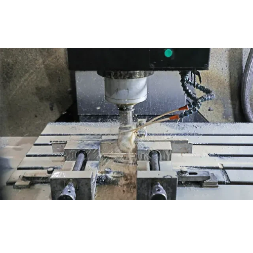
CNC milling and turning integration solves these precision challenges. A sheet metal part must be routed to a CNC mill or lathe when the design demands perfectly flat mating surfaces, precise bearing fits, or tapped holes with positional tolerances that punching or laser cutting cannot hold. Machining removes material to achieve exact dimensions, compensating for the natural variations introduced during bending or welding. We often see heavy-gauge brackets welded together and then placed in a 5-axis mill to face the mounting pads perfectly flat.
Vendor consolidation offers a significant procurement advantage. Utilizing a fabrication partner who houses both sheet metal processing and CNC machining under one roof minimizes handling, reduces transit times, and eliminates alignment errors between different facilities. Single-source manufacturing ensures the datum points used during bending perfectly align with the fixturing used during secondary machining.
Reduces overall lead times by eliminating inter-facility shipping.
Ensures accountability for final part tolerances rests with a single vendor.
Allows machinists and press brake operators to collaborate on fixturing strategies.
Lowers the risk of transit damage on delicate, thin-gauge assemblies.
Joining complex sheet metal parts presents a direct conflict between achieving maximum joint strength and maintaining dimensional accuracy. The heat required to melt metal inevitably causes expansion and contraction. This leads to severe warping in thin-gauge enclosures or precision brackets. You must balance the structural load requirements with the cosmetic and dimensional constraints of the print.
Thermal joining requires careful evaluation. TIG welding offers precise control and clean welds, making it suitable for visible cosmetic seams on stainless steel or aluminum. MIG welding provides speed and deep penetration for thicker structural components, laying down heavy filler wire quickly. However, laser welding is frequently required for thin-gauge complex parts. Laser welding minimizes heat input, creates an extremely narrow HAZ, and drastically reduces the thermal distortion that ruins tight-tolerance assemblies. It allows operators to weld 0.040" stainless steel without turning the part into a warped mess.
Cold joining provides a necessary alternative to welding. Pressure riveting techniques, self-clinching hardware, and structural blind rivets eliminate heat entirely. Cold joining is mandatory when assembling dissimilar metals, which cannot be welded together due to differing melting points. It is also required for pre-coated materials where welding destroys the galvanized or painted finish. Hardware insertion presses threaded fasteners directly into the sheet metal. The press forces the sheet metal to cold-flow into the undercut of the fastener, locking it in place and providing robust load-bearing threads in materials too thin to tap.
Specific sectors dictate the processing workflow through strict regulatory and performance standards. Evaluating these requirements early prevents compliance failures during final inspection. You cannot apply commercial-grade fabrication standards to a flight-critical component.
Across various sheet metal manufacturing industries, the aerospace and defense sector imposes the most rigorous demands. Processing workflows must include complete material traceability, NADCAP-certified special processes, and non-destructive testing (NDT) of welds. Every bend, cut, and joint must withstand extreme vibrational and thermal stresses. Fabricators must retain material test reports (MTRs) for years to prove the exact chemical composition of the metal used.
Medical device manufacturing mandates specific finishing processes, such as electropolishing and passivation, to ensure sterility and biocompatibility. These finishing requirements limit permissible cutting and joining methods. For example, welds must be perfectly smooth and free of porosity to prevent bacterial growth. This often requires automated orbital welding or high-precision laser welding followed by aggressive grinding and polishing.
The electronics and telecom industries demand high levels of EMI/RFI shielding. This requirement dictates specific plating processes, like zinc or nickel plating, and tight-tolerance hardware insertion to ensure secure grounding and continuous electrical contact across assembled panels. Processing workflows here prioritize precision punching for ventilation arrays and exact hardware placement for circuit board standoffs.
Common processing failures often stem from design choices that ignore material physics. Specifying bend radii that are too tight for the material thickness causes immediate cracking along the outside of the bend line. Placing holes, slots, or cutouts too close to the bend line results in feature distortion as the metal stretches during forming. The hole pulls into an oval shape, rendering it useless for hardware insertion. Additionally, over-specifying tolerances beyond the physical capabilities of the chosen processing method guarantees production delays and cost overruns.
Risk mitigation relies entirely on the Design for Manufacturability (DFM) review. Partnering with a fabricator who conducts rigorous DFM analysis is essential. Engineers utilize simulation software to predict springback, identify potential tearing zones, and detect tool collisions before a single sheet of metal is cut.
Import the customer CAD model into bending simulation software.
Apply the specific material properties and thickness to the model.
Unfold the model to generate the flat pattern using the shop's specific K-factors.
Simulate the bending sequence to check for press brake tooling collisions.
Adjust hole placements or add relief cuts to prevent material tearing.
DFM transforms a theoretical CAD model into a viable physical product by adjusting flat patterns, relocating features away from stress zones, and optimizing the design for the specific machinery on the factory floor.
Successfully manufacturing complex sheet metal parts requires treating the processing workflow not as a sequence of isolated steps, but as an interdependent system. Material properties, cutting precision, forming methods, and secondary machining heavily influence one another. A failure to account for the thermal impact of a laser cut will inevitably compromise the accuracy of a subsequent CNC bend. When evaluating fabrication partners, prioritize those who demonstrate deep expertise in DFM, possess advanced hybrid capabilities, and offer alternative cold-joining methods to mitigate thermal distortion.
To optimize your next production run, take the following steps:
Export your flat patterns and 3D models as STEP files for a comprehensive manufacturability review.
Audit your current prints to verify that all hole placements respect the minimum distance from bend lines.
Request a material test report from your fabricator to confirm alloy grain direction aligns with your required bend axes.
Consolidate your vendor list by identifying partners who handle both laser blanking and secondary milling in the same facility.
A: Fiber laser cutting delivers the highest accuracy for thin to medium-gauge metals. It holds tight tolerances and produces clean edges. For thicker plates or heat-sensitive alloys, waterjet cutting provides superior precision because it eliminates the heat-affected zone entirely.
A: Thickness dictates your equipment tonnage, cutting method, and minimum bend radii. Thicker plates require larger bend radii to prevent outer-face cracking. They also demand higher-wattage lasers for blanking and heavy-duty MIG welding rather than cold-joining techniques.
A: Tolerance stack-up happens when a part requires multiple sequential bends. The slight angular or dimensional error from the first bend carries over to the next. This compounding error amplifies through each step, potentially causing the final flange to miss its required tolerance window.
A: You should use cold joining when working with thin-gauge metals that warp easily under welding heat. It is also mandatory for joining dissimilar metals or pre-plated materials where thermal welding destroys the surface finish. Hardware insertion creates strong load-bearing threads in thin sheets.
A: Industries ensure repeatability by utilizing automated CNC equipment, implementing strict first-article inspection protocols, and using precision-ground tooling. Fabricators also rely on robotic welding cells and automated panel benders to remove human error from high-volume production runs.
A: No. Highly reflective materials like pure copper can damage older CO2 lasers, though modern fiber lasers handle them better. Brittle materials or metals with specific tempers may crack during CNC bending unless you apply large radii or heat the material prior to forming.


