 注: 建议图片大小150px*50px

丨
English
注: 建议图片大小150px*50px Views: 0 Author: Site Editor Publish Time: 2026-08-04 Origin: Site


Engineers frequently fall into a specific trap during the design phase. They apply default, ultra-tight machining tolerances to sheet metal designs. This simple CAD title block error unnecessarily inflates costs and extends lead times. Tolerances represent the maximum limits for dimensional variation before a part is considered out of spec. Sheet metal requires a completely different baseline than machined block metal. You cannot treat a bent piece of 14-gauge steel like a milled block of aluminum. Over-specifying tolerances, such as applying a blanket ±0.005" (0.127mm) across an entire drawing, creates major manufacturing hurdles.
This practice leads to high rejection rates on the shop floor. Fabricators must perform excessive tooling setups and run test bends to chase impossible numbers. This creates friction between design and manufacturing teams without actually improving the final enclosure performance. We need a better framework. You must evaluate which specific features demand tight tolerances, like mounting points and environmental seals, while relaxing non-critical dimensions. This strategic approach ensures a perfect balance between functional reliability and cost-effective production.
Process dictates precision: Laser cutting can reliably hold ±0.005″ to ±0.010″ (0.127mm to 0.254mm), but forming and bending inherently require wider tolerances (typically ±0.015″ to ±0.030″) due to material behavior.
Strategic relaxation saves money: Loosening non-critical dimensions (like overall enclosure width) while strictly controlling critical interfaces (like PCB mounting holes) drastically reduces fabrication costs.
Material selection is a variable: Raw material thickness variations (gauge tolerances), grain direction, and springback properties directly impact the final dimensional accuracy of the enclosure.
Cumulative tolerances matter: Bend-to-bend stack-ups must be calculated during the design phase to prevent fitment issues in multi-part assemblies.
Engineering schools teach a standard baseline tolerance of ±0.005 inches for three significant figures. This works perfectly for CNC machining where rigid blocks of metal are cut with spinning end mills. However, it is entirely unrealistic for overall sheet metal processing. Sheet metal begins as a flat, flexible material. It undergoes thermal stress during laser cutting and immense mechanical stress during press brake bending. Forcing a fabricator to meet unyielding title block tolerances on non-critical features carries heavy penalties.
When a CAD designer drops a standard title block onto a sheet metal drawing without updating the default tolerances, the quality assurance department is forced to reject parts based on those numbers. The shop must slow down production to monitor every single bend. Operators might need to add secondary machining operations just to shave a few thousandths off a bent flange. They end up performing 100% manual inspection rather than relying on statistical process control. These temporal penalties delay your product launch. If the overall width of a server chassis is off by ±0.015 inches, it rarely affects the final assembly. Yet, a blanket title block tolerance forces the fabricator to scrap that perfectly functional part.
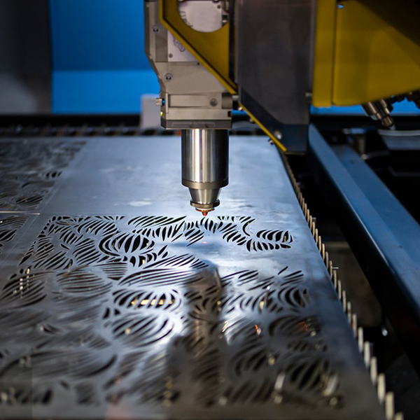
Flat pattern cutting offers excellent precision. Modern fiber lasers and CNC punching machines can reliably hold tolerances between ±0.005″ and ±0.010″. Hole diameters, complex cutouts, and edge-to-edge flat dimensions remain highly controllable. The laser beam has a consistent kerf width, and assist gases like nitrogen or oxygen ensure a clean edge. The material lies flat on the cutting bed, eliminating gravity-induced deflection.
Press brake forming introduces entirely different mechanics. Bending metal stretches the outer radius and compresses the inner radius. Tolerances must open up, typically ranging from ±0.010″ to ±0.030″. Air bending is the most common method on the shop floor. The punch presses the metal into the V-die without bottoming out. This relies heavily on the press brake's depth accuracy and the material's consistency. Tooling geometry plays a massive role here. The V-die width and punch radius dictate how the material flows. Tool wear over time introduces natural dimensional variations. A punch that has bent 10,000 parts will behave differently than a brand-new tool.
High-volume stamping contrasts sharply with low-volume press brake fabrication. Hard-tooled stamping uses dedicated dies to strike the metal under immense tonnage. This process achieves tighter, highly repeatable tolerances for critical features, often between ±0.1mm and ±0.5mm. However, the upfront tooling cost is massive. Stamping only makes financial sense for mass production runs. Standard press brake forming remains the go-to for low to medium volumes.
A major disconnect exists in product development. Engineers often expect flat-cutting tolerances on formed features. They design a bent flange and demand ±0.005″ accuracy from the bend line to the edge. This expectation creates immediate manufacturing bottlenecks. The fabricator must spend hours tweaking the press brake backgauge to hit an impossible target.
Table 1: Standard Sheet Metal Tolerance Expectations
| Manufacturing Process | Typical Tolerance Range (Inches) | Typical Tolerance Range (mm) | Primary Application |
|---|---|---|---|
| Laser Cutting (Flat) | ±0.005″ to ±0.010″ | ±0.127 to ±0.254 | Hole diameters, flat profiles, cutouts |
| CNC Punching (Flat) | ±0.005″ to ±0.010″ | ±0.127 to ±0.254 | Perforations, extruded holes, louvers |
| Press Brake Forming | ±0.015″ to ±0.030″ | ±0.381 to ±0.762 | Flanges, brackets, overall bent dimensions |
| Hard Tool Stamping | ±0.004″ to ±0.020″ | ±0.100 to ±0.500 | High-volume mass production features |
| Secondary Machining | ±0.001″ to ±0.005″ | ±0.025 to ±0.127 | Critical mating surfaces, tapped holes |
Internal components require precise alignment. Printed circuit boards (PCBs), DIN rails, and heavy power supplies must bolt seamlessly into the chassis. This makes hole-to-hole accuracy a high-priority tolerance zone. If mounting holes misalign by even a fraction of a millimeter, assembly line workers cannot install the hardware without modifying the parts on the fly. Self-clinching fasteners, like PEM nuts and standoffs, also demand tight hole tolerances. If the laser-cut hole is too large, the knurl will not bite into the sheet metal, causing the hardware to spin out during final assembly.
The solution relies on smart design. Place all critical mounting holes on the same flat plane. This strategy utilizes highly accurate cutting tolerances rather than unpredictable bending tolerances. When holes sit on the same flat face, the laser cuts them in a single setup. The relationship between those holes remains locked at ±0.005″.
If you must mount components across multiple bent flanges, use slots or oversized holes. A circular hole on one flange and an elongated slot on the mating flange absorb tolerance stack-up. This simple adjustment guarantees fitment without forcing the fabricator to hold unachievable bend dimensions.
Outdoor environments demand strict ingress protection. Successful industrial enclosure applications rely on proper seal compression to keep dust and water out. You must control the tolerances of the mating surfaces that crush the gasket. Enclosures designed for IP65 or NEMA 4X ratings must withstand high-pressure water jets. The gasket must compress uniformly by 25% to 30% depending on the material.
Bend angles and flange lengths directly impact gasket compression. If a door flange bends at 88 degrees instead of 90 degrees, the gasket pinches unevenly. A one-degree variation on a one-inch flange moves the edge by approximately 0.017 inches, which can easily compromise a narrow gasket. Polyurethane poured-in-place (FIP) gaskets and EPDM foam strips require a specific compression percentage to function. Too much compression destroys the foam memory. Too little compression allows water ingress.
Door seams and overlapping joints require specific tolerance controls. The gap between the door and the main body must remain consistent across the entire perimeter. If the door warps due to tight bend tolerances fighting against material stress, the seal fails. Specify a generous gap that the gasket can easily bridge, rather than aiming for a near-zero clearance fit.
Cumulative tolerance, or tolerance stack-up, occurs when multiple bends chain together. Every time the press brake bends the metal, it introduces a small error. In a multi-bend part like a U-shape or a complex chassis, these errors add up quickly.
Fabricators typically account for approximately ±0.015″ to ±0.020″ of variation from bend to bend. Consider a U-channel bracket with three consecutive bends. If each bend carries a ±0.015″ tolerance, the cumulative tolerance easily reaches ±0.045″ by the final flange. Expecting the last flange to align perfectly with a mating part based on a chained dimension is a recipe for failure.
You can mitigate this risk through datum dimensioning. Follow these steps to control stack-up:
Identify the single most critical mating surface on the enclosure.
Establish this surface as the primary datum edge on your CAD drawing.
Dimension all critical features directly from this single datum edge.
Avoid chaining dimensions from one bend to the next.
Allow the non-critical flanges at the end of the part to absorb the excess variation.
Sheet metal does not arrive from the mill with a perfect, uniform thickness. A standard gauge varies by several thousandths of an inch. For example, 16-gauge cold-rolled steel has a nominal thickness of 0.0598 inches, but the acceptable mill tolerance ranges from 0.0548 to 0.0648 inches.
This raw material variation directly affects the fabrication process. Engineers must understand the K-factor. The K-factor represents the location of the neutral axis within the material thickness during a bend. Since gauge thickness varies, the K-factor shifts. The inside bend radius changes based on the actual thickness of the sheet. The press brake operator calculates a bend deduction to determine the flat pattern size. If the material runs thick, the bend deduction changes. This variation ultimately alters the final outside dimensions of the enclosure. You cannot achieve ±0.005″ precision when the raw material itself varies by ±0.005″.
Table 2: Standard Cold-Rolled Steel Gauge Variations
| Gauge Size | Nominal Thickness (Inches) | Minimum Thickness (Inches) | Maximum Thickness (Inches) |
|---|---|---|---|
| 12 Gauge | 0.1046 | 0.0966 | 0.1126 |
| 14 Gauge | 0.0747 | 0.0697 | 0.0797 |
| 16 Gauge | 0.0598 | 0.0548 | 0.0648 |
| 18 Gauge | 0.0478 | 0.0438 | 0.0518 |
The rolling process at the steel mill creates a visible grain direction in the sheet metal. This grain behaves much like the grain in wood. It significantly influences bending accuracy and structural integrity.
Bending parallel to the grain (with the grain) increases the risk of cracking, especially in harder materials. It also alters how the material forms around the punch tip, changing the bend radius. Bending perpendicular to the grain (across the grain) yields a stronger, more predictable radius. Fabricators must adjust flat patterns and tolerances based on grain orientation. If your design requires bends in multiple directions, the fabricator must compromise, which naturally opens up the tolerance window.
Proper enclosure material selection dictates forming accuracy and repeatability. When the press brake releases pressure, the metal tries to return to its original flat state. This phenomenon is called springback.
Different materials exhibit different springback characteristics:
Cold Rolled Steel and Carbon Steel: These materials offer predictable behavior. They experience minimal springback, making it easier for operators to hold tighter bend tolerances consistently without running multiple test pieces.
Aluminum (e.g., 5052-H32): Aluminum presents moderate springback. It is prone to cracking if bent over a sharp radius. Operators must use larger punch radii, which slightly reduces dimensional precision compared to steel.
Stainless Steel (e.g., 304 and 316): Stainless steel has high tensile strength. This results in significant springback. The operator must over-bend the material considerably to achieve a 90-degree angle. This requires wider bend tolerances and specialized tooling compensation to hit the target dimensions.
You should only pay a premium for tight tolerances when the design absolutely requires them. Specific scenarios justify the extra cost in sheet metal enclosure fabrication. Press-fit hardware insertion demands precise hole diameters. Critical connector cutouts, like USB or Ethernet ports, require tight profiles to ensure proper mounting. EMI/RFI shielding contact points need perfectly flat mating surfaces to prevent signal leakage.
Fabricators achieve these tight tolerances through expensive methods. They use precision-ground tooling. They slow down processing speeds to monitor the output closely. In some cases, they perform secondary machining operations, like milling a bent flange flat, to hit the required number. These steps add significant labor and machine time to your invoice.
You must identify features where tolerances can safely open up. Overall exterior dimensions of a large cabinet rarely need extreme precision. Cosmetic flanges that do not mate with other components can easily absorb a ±0.030″ variation. Cable routing holes and internal ventilation cutouts function perfectly well with relaxed dimensions.
Relaxing these tolerances delivers a direct value outcome. The fabricator can use standard, off-the-shelf tooling. They can run the press brake at faster production rates. They spend less time tweaking the setup and inspecting parts. The shop passes these cost savings directly to the buyer. A design with intelligently relaxed tolerances moves through the manufacturing floor quickly and economically.
You can reduce tolerance-related failures by applying strong Design for Manufacturability (DFM) principles. Utilize relief cuts at bend intersections. A proper bend relief prevents the material from tearing and distorting when two adjacent flanges fold upward. Avoid placing holes or cutouts too close to the bend line. If a hole sits in the deformation zone, it will stretch and pull out of tolerance during forming. Maintain a minimum flange length of at least four times the material thickness to ensure the metal sits securely across the V-die during bending.
Standardize your bend radii across the entire design. Using a single inside radius allows the fabricator to form the entire part with one tooling setup. This eliminates tool changeovers and reduces the chance of setup errors. Emphasize early collaboration. Involve your fabrication partner during the CAD phase before finalizing the drawing. They can spot tolerance traps and suggest minor geometry changes that drastically improve manufacturability.
Mismatched measurement methodologies cause massive headaches. You might measure a flexible sheet metal flange with hand calipers, squeezing the material and altering the dimension. The fabricator might measure that same flange using a Coordinate Measuring Machine (CMM) or a non-contact laser scanner. These different methods yield different results, leading to false rejections.
Establish a clear Quality Assurance (QA) and First Article Inspection (FAI) protocol upfront. Explicitly define how critical dimensions will be measured. Agree on the specific tools used for verification, whether that involves hard gauges, optical comparators, or height gauges. Document how the part will be restrained during measurement. A flexible 24-inch panel will sag under its own weight. If the QA inspector rests the part on a granite surface plate without proper fixturing, the height measurement will fail. Aligning these criteria ensures that both parties verify the maximum allowable limits using the exact same standards.
Audit your existing CAD files to locate and remove blanket ±0.005" title block tolerances on all formed sheet metal components.
Redimension your multi-bend enclosure drawings using a single datum edge to eliminate cumulative tolerance stack-up.
Update your manufacturing prints to specify relaxed tolerances of ±0.030" on non-mating exterior dimensions and cosmetic flanges.
Schedule a design review with your fabrication partner to establish agreed-upon measurement methods and First Article Inspection protocols.
A: Standard tolerances depend entirely on the manufacturing process. Flat laser cutting and CNC punching defaults typically range from ±0.005″ to ±0.010″ (0.127mm to 0.254mm). Forming and bending defaults require wider allowances, usually between ±0.015″ and ±0.030″ (0.381mm to 0.762mm). Applying tight cutting tolerances to bent features is a frequent design error that inflates production costs.
A: Bending introduces multiple unpredictable physical variables. Material thickness varies directly from the steel mill, which alters the inside bend radius. The grain direction of the sheet affects how the metal stretches over the die. Additionally, different metals exhibit varying degrees of springback when released from the press brake tooling, requiring constant operator adjustment and test bends.
A: Tolerance stack-up is the cumulative dimensional error that builds across multiple consecutive bends. If each bend carries a ±0.015″ tolerance, a part with three bends could vary by ±0.045″ at the final flange. You can avoid this compounding error by using datum dimensioning, which measures all critical features from a single starting edge rather than chaining dimensions.
A: Sheet metal gauges have acceptable mill tolerances, meaning the raw material thickness fluctuates across a single batch. This variation directly alters the bend deduction calculations used to create the flat pattern. If the material runs slightly thicker than nominal, the metal stretches differently over the V-die, ultimately changing the final outside flange length of the enclosure.
A: Raw sheet metal processes cannot hold standard machining tolerances like ±0.001″. While flat fiber laser cutting is highly accurate, press brake bending inherently lacks that level of precision due to material flow and springback. You can achieve machining tolerances on sheet metal by adding secondary CNC milling operations after forming, but this exponentially increases fabrication costs.


